*Please prepare a license ID and password for the license administrator.
*It is different from the service for JMAG WEB MEMBER (free membership). Please be careful.
Overview

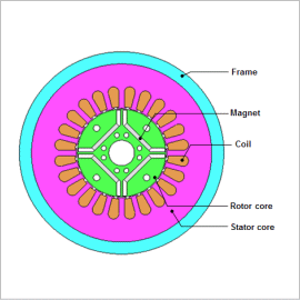
One of the demands for IPM motors is higher efficiency over a wide range of rotation speeds in combination with motor drives, as reluctance torque can be used in addition to magnet torque. Iron loss makes up a particularly large proportion of total loss in the high rotation region, and how to make this smaller is a major design issue. Generally, IPM motor cores have laminated structures, and methods such as press fitting or shrink fitting are used to maintain them.
For motors using magnetic steel sheet for their cores, the stress generated by press fitting can increase iron loss, so it is important to take this stress into account when evaluating iron loss.
Iron loss is generated when there are magnetic-field variations in steel sheet. Also, the amount of iron loss depends on the steel sheet’s iron loss properties. These iron loss properties of steel sheet become worse when it is subjected to stresses such as press fitting. The stress caused by press fitting has its own distribution, and is particularly large in the back yoke. So, in order to evaluate the iron loss with good accuracy, it is necessary to correctly obtain the stress distribution for the magnetic flux, time variation, and steel sheet.
This Application Note presents modeling the press fitting of a core and frame with the Press Fit condition and then obtaining the iron loss density of an IPM motor with and without accounting for the stress generated at that time.
Minimum Principal Stress Distribution

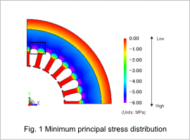
The minimum principal stress distribution is indicated in fig.1. Tensile stress occurs in the frame and teeth, but compressive stress that especially affects the iron losses is produced largely in the yoke. The compressive stress is especially large in the area of the model within the square in fig.1, but this is because of the slots’ geometry.
Iron Loss Density Distribution

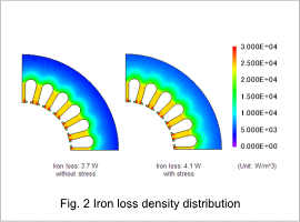
Fig.2 shows the iron loss density distribution. The iron loss density distribution varies depending on whether or not the stress is accounted for. The iron losses are increased by 10 % due to the stress. An analysis that accounts for the compressive stress caused by the press-fitting needs to be performed to evaluate the iron losses more accurately because the iron losses increase when the compressive stress is applied.


