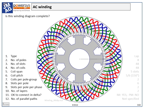
Winding diagrams come in many different formats. There is no universal standard, but several common conventions can be found in the winding diagrams used by different manufacturing companies. Many winding diagrams are incomplete, in one respect or another. For example, the example in the figure does not show any interconnectors or terminals. Consequently the polarities of the coils are not defined, although we might be able to infer them by studying the layout carefully.
To work with windings, we need terms for all the components. We have to be careful because some of the common terms mean different things to different engineers.
The example is taken from one of the Powersys/JMAG training courses, and it is presented as a question-and-answer session. The questions are summarized on the left, and the answers (very faintly) on the right. Let’s work through the questions, as a way of understanding the diagram and the terminology at the same time.
1. The winding type. The most common windings in larger AC machines are lap windings. In a lap winding, all the coils are the same. Each coil occupies two slots (a “go” slot and a “return” slot) whose numbers are 1 more (or 1 less) than the slot-numbers of the previous coil. For example, coil 1 is in slots 1 and 6, and coil 2 in slots 2 and 7. The “1 more” succession characterises a progressive lap winding, and the “1 less” succession a retrogressive lap winding. The distinction is not particularly important in AC windings, so these terms are not used as often as they are in commutator motors. Other types of winding used in AC machine stators include concentric windings (common in hermetic single-phase induction motors and others where the windings are made by automatic insertion tools). There are several terms relating to the method of manufacture, such as form winding, mush winding, random winding, skein winding, chain winding, and so on. None of these appears in the diagram! Another common term is concentrated. This used to refer to pole-groups with “zero spread” — that is, all the “go” coil-sides and all the “return” coil-sides concentrated in the same two slots. However, in recent years the term has often been used for single-tooth windings (which are concentrated in the original sense).
2. The number of poles. This is easily seen to be 8, by counting the salient poles on the field winding on the rotor. But that’s cheating — the rotor is not part of the winding diagram! It might be easier to answer some of the other questions first, and then come back to the number of poles.
3. The number of slots. Easy — 48! Count them. But even here we need to be careful because not all winding diagrams show the outline of the stator lamination, and some even do not show all the coils. In fact we’ve seen in an earlier column that some winding diagrams apply to windings with more than one possible number of slots and coils. In general the number of slots must be divisible by the number of phases (in this case, 3) to ensure that a symmetrical or balanced winding is possible, and here it must be even to ensure that all the “go” and “return” coil-sides are disposed evenly. Odd numbers of slots are sometimes used in DC motors with wave windings.
4 and 10. The number of coils. A coil has two coil-sides, laid in different slots which can be termed the “go” slot and the “return” slot, as we have seen. In the example every slot contains two coil-sides, and therefore the number of coils is equal to the number of slots, 48. The number of layers is usually equal to the number of coil-sides per slot, but we have to be careful because some special windings have different numbers of coil-sides in different slots.
5 and 6. The coil span is the number of slots between the “go” coil-side and the “return” coil-side. In this case all the coils are identical and they have a span of 5 slots; so for example coil 1 “goes” in slot 1 and “returns” in slot 1+5 = 6. (It would help if the draughtsman numbered the slots, but he didn’t). The coil pitch is equivalent to the span, except that this term is used more often in a theoretical context and expressed in electrical degrees, or per-unit of a pole-pitch. Since this machine has 8 poles and a pole-pitch of 48/8 = 6 slots, the coil pitch here is 5/6 = 0·833 p.u., or 5/6 × 180° = 150 electrical degrees. These values are essential for calculating the winding factors and the harmonic behaviour of the winding. In some factories another term, “coil-throw”, is used to define the span. A coil with a span of 5 slots would be described as having “Throw = 6”, meaning “wound or laid in slots 1 and 6”. We have to be careful not to confuse the “6” with the “5”. Finally the sign of the coil-span may be important. For example a winding defined in terms of a series of “go” slot numbers with a positive span could be described as “progressive”, while with a negative span it would be retrogressive. This terminology would be more meaningful in the winding shop, but in analysing the electrical and harmonic properties we would tend to use the coil pitch, which also can be positive or negative. In formulas for the distribution and pitch factors the sign of the coil pitch is often omitted, but in rigorous harmonic analysis it should be included, because it affects the phase sequence and direction of rotation of harmonic field components. Finally as we have seen elsewhere in this column, the polarities of the individual coils are generally defined by the interconnectors. In some winding diagrams we will see coil-spans alternating between positive and negative; but if that is done, it may be left to the poor reader to work out the interconnectors, and it should be considered poor practice.
7. Coils per pole-group. First we have to observe that the coils of one phase arise in groups, each group being aligned with one pole. In the example there are 48 coils, 8 poles, and 3 phases, so there are 48/3 = 16 coils per phase and the number of coils per pole-group is 16/8 = 2. There are 16/2 = 8 pole-groups per phase. In some cases, by the way, alternate pole-groups are omitted; this type of winding is called consequent-pole. The identification of pole-groups is easy in the example, which has a nice integer number of slots/pole (6); but some windings have fractional slots/pole, and the number of coils per pole-group may vary or form a sequence such as 5,6,5,6,. . . In small PM brushless machines with a small number of slots, the number of coils per pole-group is often only 1.
8 and 9. Slots/pole and slots/pole/phase. The slots/pole is clearly 48/8 = 6, an integer. It should be divisible by the number of phases (3), so slots/pole/phase = 6/3 = 2. Such regular integer values are characteristic of classical AC windings, and usually we find the number of slots/pole/phase in the formula for the winding distribution factor; a higher value (such as 4 or 5 or 6 or even more) is generally an indication of good harmonic performance — that is, sinusoidal flux-distribution with weak harmonic effects. The number of slots/pole is often an indicator of the cogging torque, and this is one of the reasons why brushless PM machines often use fractional values; in addition, when single-tooth coils are used, the slots/pole is often found to lie between 0·75 and 1·5.
11. Is it OK to connect in delta? This question should be considered slightly differently for PM brushless (or other synchronous) machines, and induction machines. In the synchronous machines the field (magnets or field winding) may produce a third-harmonic component in the airgap flux distribution, and in this case it is vital for the third-harmonic winding factor to be zero. Generally this is achieved by setting the coil pitch equal to 2/3 p.u. (120 electrical degrees). In the example the coil pitch is 5/6; the third-harmonic winding factor is not zero and so the winding does not filter the third-harmonic completely. Consequently if it is connected in delta there will be a non-zero EMF around the delta, since the third-harmonic EMFs in the three phases are all in phase. The impedance to this EMF is generally small, so a large circulating current may flow, which is not observable at the terminals. Overheating or even fire may result. So this winding must not be connected in delta with a PM rotor. With an induction machine, however, the source of third-harmonic flux is much reduced, and a delta connection may be acceptable if thoroughly tested under all operating conditions, and taking possible manufacturing errors into account (such as eccentricity of the rotor, any residual saliency in the rotor, or imbalance between phases).
12. The number of parallel paths. Provided that symmetry is observed, the maximum number of parallel paths (in each phase) is generally equal to the number of pole-groups per phase, in this case 8. However we could also use 2 or 4, by interconnecting pole-groups in series/parallel combinations. If all the coils of one phase are in series, the number of parallel paths is just 1. The diagram does not specify the number of parallel paths — it doesn’t even show the interconnectors! Note that we must be careful not to confuse the number of parallel paths with the number of parallel wire strands in each conductor; the two are entirely separate properties. Changing the number of parallel paths is a common way to adapt the machine for different voltage levels with minimal changes to the winding.
Finally let’s reconsider the number of poles. Can we infer it from the coil span, or the number of pole-groups? It’s a good exercise to see if we can do that. With cage-type induction motors, we won’t get any help from the rotor!
As an extended exercise, the reader may be interested to make a winding diagram for this machine in your own style, perhaps adding interconnectors and even calculating the harmonic winding factors. (The fundamental winding factor is 0·9330). Or you might care to comment on the example diagram, and suggest improvements!

