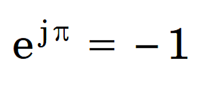
Euler [1707-1783] is closely associated with this equation which has been described as the most beautiful equation in mathematics. It is sometimes regarded as having mystical significance; at the very least, it contains a great deal for the pure mathematicians to ponder. Not only does it relate the five elements 0, 1, e, j and π in an apparently simple and elegant formula; but it also leads to the precept j = √(−1), which undoubtedly makes it even more mystical.[1]
As electrical engineers we can claim to be members of a very small elite for whom Euler’s equation is something we use every day. Indeed we would know it as a special case of the equation

with θ = π, and we would interpret the function ejθ in general as a rotation through angle θ.
Rotation of what?
The obvious mathematical answer is any complex number, but what do complex numbers mean in engineering? We can list three examples from the world of AC drives and machines:
(ii) space vectors
(iii) MMF vectors
These items are actually very different, but they are all represented by complex numbers and they are often closely related in calculations.
(i) Phasors, also used in AC circuit theory and power systems analysis, provide a compact notation for calculations involving harmonic functions of time: that is, sinusoidal waveforms of voltage, current, flux-linkage, and sometimes field quantities such as current-density, vector potential, or flux-density. It is not simply a matter of shorthand. The theory of AC circuits in the steady state makes heavy use of what mathematicians would call the elementary rules of complex algebra — addition and subtraction to deal with series and parallel circuits; division (of voltage and current phasors) to formulate complex impedances; and the product of complex voltage and the conjugate of complex current to calculate real and reactive power. These operations extend to cover distorted periodic waveforms in terms of their harmonics extracted by Fourier series in the steady state; and even to the study of transients by means of the Fourier and Laplace transforms.
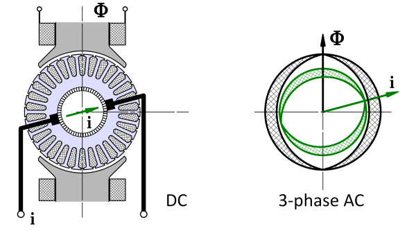 Fig. 1 Space-vector concept
(ii) According to Professor Leonhard, space-vectors were introduced in the 1950s. The name of Kovács in Hungary is particularly associated with some of the early disclosures, and they can be shown to be mathematically related to the “instantaneous symmetrical components” described by Lyon [1954] and Ku [1959]. But the space-vector should really be seen in its own right as compact notation describing the combined effects of currents, voltages and flux-linkages in sinusoidally-distributed polyphase windings. Fig. 1 expresses a related idea for current and flux in a DC machine in which the flux axis is fixed while the armature reaction axis is defined by the brush axis. While this may be an intriguing historical analogy, our attention should be drawn instead to the inventive mathematical process that led to the field-orientation principle and its derivatives, Blaschke [1971]. This principle requires more space than we have here, but we can introduce the definition of a space-vector and we can recognize that it provides the natural language for the contemporary control theory of AC machines. In a 3-phase machine we generally have three instantaneous currents, three complex phasors, three components in dq0 axes or fb0 axes, or three symmetrical components. Wouldn’t it be good to have a single number that represents “the stator current”, and likewise for voltage and flux-linkage? The space-vector provides this single number, and Fig. 2 shows a numerical example of the construction of the space-vector is from three phase currents.
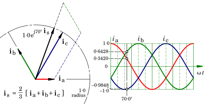 Fig. 2 Space-vector construction example
We can summarise two important properties of space-vectors as follows. Although they are complex numbers, like phasors, they have two major differences:
- Space-vectors represent the spatial orientation of ampere-conductor and flux distributions within the machine, as well as their amplitudes;
- Unlike phasors, space-vectors can vary rapidly in time and are not restricted to steady-state sinewave operation. Indeed, rapid variation is inherent in fast dynamic response in a motion-control system where speed and torque can change rapidly.
The space-vector also has the remarkable property of being able to describe the instantaneous switching state of an inverter. It thus unites the continuous variables of machine behaviour with the discrete variables of its switchmode controller. This facilitates interaction between engineers working in machine design, power electronics, and control, giving them a common language and a unity that could hardly be achieved by any other means.
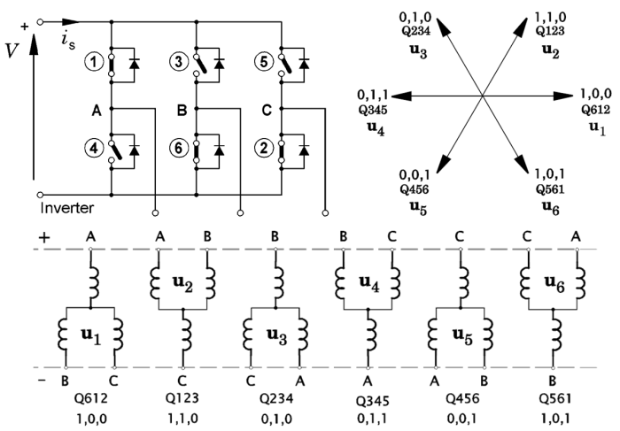 Fig. 3 Space-vector representation of inverter switching
In Fig. 3 the six inverter transistors are numbered in the usual “order of firing”. Six circuit diagrams show the connection of the windings across the DC supply, according to the states of the switches. From these, six voltage space-vectors are defined from the voltages of the phase terminals A,B&C; these are shown at upper right. Two different notations are used to define the switch states. Thus Q612 means that transistors 6,1,&2 are on, while transistors 3,4&5 are off. In the other notation 1,0,0 means that in phase-leg A the output terminal is connected to the positive rail while the output terminals of phase-legs B and C are connected to the negative rail.
The space-vector of all three phase currents can be “persuaded” to follow a circular locus by PWM (pulse-width modulation), in which the inverter switches at a high frequency (the “carrier” frequency) between nearby states in Fig. 3, varying the duty-cycle so that in a time-averaged sense, the applied voltage has a fundamental-frequency component that is just what is needed to force the required current. The process generally employs digital current regulators: that is, feedback loops in which the current is made to follow a reference waveform. This process is very sophisticated with features such as phase advance for flux-weakening at high speed, and energy-saving features that minimize harmonics and switching losses. The motor inductance helps to attenuate the carrier-frequency ripple in the current waveform, so that the current waveforms are remarkably smooth.
Normally a finite-element field analysis is not required to respond with field calculations at anything like the carrier frequency. But it is critical at the fundamental frequency, so that the correct reference current and phase angle can be estimated at each load point. The process is often conducted in dq axes, that is, reference axes fixed to the rotor, so that the main values are DC values in the steady state. The calculations of the required mappings for the control variables are often accompanied by detailed finite-element analysis of parasitic effects including core losses and eddy-current losses in magnets. Usually these ancillary calculations, important as they are, do not need to be coupled to the torque calculation or even synchronized with it. The architecture of control models in dq axes generally has interfaces for the exchange of parameters related to the parasitic effects.
(iii) Finally, the third application of complex numbers mentioned at the beginning is the MMF vector. There isn’t space to go into detail here, so maybe we’ll discuss it in a future Diary. Briefly, the MMF vector describes the space-vector of a particular harmonic of the ampere-conductor distribution, either of one phase or of all three phases, and sometimes of only one coil. The MMF vector is closely related to the “slot star” used in the theory of AC windings, and it is found in the calculation of harmonic leakage inductance and the Görges diagram. Unlike the conventional space-vector, the MMF vector is not based on the assumption of sine-distributed windings, but treats the individual harmonics of the actual winding, on a coil-by-coil basis.
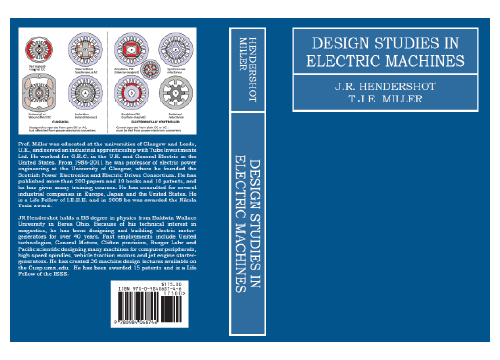
All these complex-number concepts and applications are described in chapter 14 of the forthcoming “blue book”, Design Studies in Electric Machines, which is expected in the next few months.
Note :
[1] j is used in electrical engineering because i is reserved for current.
References :
- Blaschke, F., Das Prinzip der Feldorientierung, die Grundlage für die TRANSVEKTOR-Regelung von Asynchronmaschinen, Siemens Zeitschr. 45, p. 757, 1971.
- Ku Y.H., Electric Energy Conversion, Ronald Press, New York, 1959.
- Lyon W.V., Transient Analysis of Alternating-Current Machinery, M.I.T. Press and John Wiley, New York, 1954.
Please also see :
- Yamamura S., Spiral vector theory of AC Circuits and Machines, Oxford University Press, Oxford, 1992.
Actually I remembered the work of Prof. Yamamura after I sent the draft yesterday. I think his work is not so well known outside Japan, but it certainly has some fascinating insights (like Ku [1959]). I do not know if it is widely used. I did not dare to discuss the spiral vector in the Diary, because I’m not so familiar with it, and I think it could introduce confusion in what is already quite a complex topic. At the time Professor Yamamura’s book was published, I was one of the technical editors of the Oxford University Press series, and I remember that O.U.P. were keen to publish it, even through it was not well known at that time. T.J.E Miller

