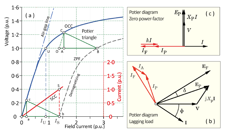
Fig. 1 Synchronous machine charateristics including the Potier triangle
The work of Alfred Potier (1840-1905) belongs securely in the foundations of the theory of the wound-field synchronous machine, [1].
The wound-field synchronous machine is very old, very important, very common, and very saturable. So how did engineers calculate its operational performance characteristics before the days of finite-element analysis?
The historic classical methods should not be brushed aside on the grounds that finite-element analysis can produce results without them. Many of the concepts developed with those methods are still in use today, including the concepts of synchronous reactance, two-axis theory, the phasor diagram, and for transient and fault calculations, the transient and subtransient reactances and their associated time-constants. It is probable that none of these concepts would emerge naturally from finite-element calculations, if the precedents had not been set in the classical era. All of these concepts are deeply established in the terminology and characterization of synchronous machines. Indeed some of the concepts and parameters, and several of the standard tests, are enshrined in international standards such as IEC 60034 and IEEE 115, and their national equivalents.
But another reason to value the classical methods is the insight they give, concerning the nature of the field-analysis problem and the circuit behaviour. This physical insight is to a certain extent helpful in visualizing the internal operation of the synchronous machine, although modern finite-element analysis goes much further.
The Potier diagram
Central in the theory of the steady-state operation of the synchronous machine is the Potier diagram, shown for an overexcited nonsalient-pole generator with a lagging load in Fig. 1(b). The diagram has voltage phasors on the right, and MMF vectors coloured red on the left.1 The MMF vectors are expressed in terms of actual or equivalent components of field current, even though field current is a DC quantity. Among other things, Fig. 1(b) expresses the correspondence between sine-distributed field quantities distributed in space around the air-gap (on the left), and the time-waveforms of the fundamental harmonic components of voltages and currents in the phasor diagram (on the right). It is all too easy to take this correspondence for granted,2 yet it underlies the dq0-axis transformation, the αβ0 (Clarke) transformation [4], and the theory of space-vectors, [2].
The problem in the steady-state analysis of the synchronous machine is to calculate the combined effect of the excitation (field current, rotor current) and the armature reaction (stator current flowing in all three phases). There are two main difficulties. The first is that the field and armature windings are distributed differently, so they produce MMF waves of different shape around the air-gap. The resulting flux distributions are also very different, owing to the physical shape of the magnetic components, especially in salient-pole machines. (Note that the same is true in permanent-magnet machines). The second difficulty is magnetic saturation, which is usually pronounced (especially in highly rated machines). This means that fluxes cannot simply be added; not even their fundamental space-harmonics can simply be added, because ‘adding’ means ‘superposition’: although we do it all the time, we cannot do it uniquely.
The Potier triangle and the Potier reactance
Fig. 1(a) shows the open-circuit characteristic OCC, the short-circuit characteristic SCC, and the zero-power-factor characteristic ZPF (in a demagnetizing condition at rated current). Note that all these tests are conducted with the rotor rotating, and in all of them the drive motor need be large enough to provide only the losses, and not the full rated power.
The OCC relates the DC field current to the RMS value of the fundamental time-harmonic of the generated voltage on open-circuit. The SCC establishes the equivalence between the field current and the armature (stator current), and there is a ‘coefficient of equivalence’ k that appears in Fig. 1(c), the phasor diagram for the zero-power-factor (lagging / demagnetizing) condition. It is effectively a way of measuring the mutual coupling between the field winding and the combined armature windings in the d-axis. The direct measurement bypasses the complicated theoretical issues involved in relating the DC in a rotating concentrated field winding to the AC in a distributed polyphase stator winding. However, because of the very low flux levels associated with the short-circuit connection, the mutual inductance measured from the SCC (and any other coefficients of MMF balance) will refer to unsaturated conditions. Although this measurement (particularly the field current IS at rated armature current) is used in the so-called ‘MMF method’ [5,6] for the reconstruction of the on-load phasor diagram, it is acknowledged to give only approximate results.
The ZPF test is an extension of the short-circuit test, in which the driven machine is loaded with a variable inductive reactance, while the field current is varied over a certain range to maintain constant armature current. The point about the ZPF is that it characterizes the saturation characteristics of the main flux-path (the d-axis), and it can do this for both demagnetizing and magnetizing armature reaction at any level of armature current.
One of the tenets of the classical theory is that the ZPF turns out to be a replica of the OCC, but shifted downwards and to the right. This facilitates the so-called Potier triangle (BAC in Fig. 1), in which AC represents a voltage drop in a linear reactance called the Potier reactance XP, and AB represents the field current component required to overcome armature reaction at the operating point B (typically at rated voltage and rated current). This field current component is written kI for any particular armature current I. The Potier triangle thus provides two important parameters from which the field current at any other load-point is calculated by one of several alternative procedures.
It is axiomatic in applying these procedures, that
| (i) | there is a unique non-saturable ‘leakage’ reactance (the Potier reactance) in series with a saturable inductive element that represents the main magnetic flux-path (the d-axis); and |
| (ii) | the saturation properties of the main flux-path, represented by the OCC (and equivalently by the ZPF), apply under all load conditions to the inductive voltage/current relationship of the saturable inductive element. |
The ‘saturable inductive element’ will be recognized as the so-called ‘magnetizing’ part of the saturated synchronous reactance, excluding the leakage reactance (Potier reactance).
Many of the standard procedures for calculating on-load excitation at a given load-point do not actually mention synchronous reactance. They simply process the graphical data according to various procedures that go by the names ‘EMF method’, ‘MMF method’, ‘ASA method’, ‘General method’, ‘Swedish diagram’, with many variants. Some of these methods are essentially ways of combining MMFs, while others [7] transform the same calculation into an equivalent phasor diagram of voltages (often with complicated details). The methods are not standardized, even though some of them are described in the standards [5], which seem to treat them as optional depending on circumstances and available resources.
Fig. 1(b) illustrates the process in simplified form. The voltage phasor jXPI is added to the terminal voltage V, giving what is known as the ‘voltage behind the Potier reactance’ EP (sometimes called just ‘the Potier voltage’ or ‘the Potier EMF’). Most of the methods mentioned above have this first step in common, but differ in subsequent steps. However the basic method is to use the value of EP on the OCC to obtain a field current IP and to add to this an ‘armature reaction’ component IA oriented parallel to the armature current I, resulting in the final field current IF.
If you have reached this point and you are thinking ‘what a complicated, arbitrary, imprecise mess’, you can be forgiven. The description given here is rather superficial. To execute any of the methods in detail, it is necessary to study them in detail, and it is certainly not enough simply to grasp the idea of the Potier triangle: one must also learn how to apply it. A frustrating aspect of that is the fact that no matter how much care is taken, the results will only ever be approximate. They may be adequate, but the classical method for estimating on-load excitation of a synchronous machine cannot hope to compete with a fully-fledged finite-element calculation.
Nevertheless, the classical engineers did use these methods and in many cases they still do. Not only that, the literature is rich in embellishments and extensions. Some of them are quite fantastic in the amount of detail and speculative imagination. For example, heroic efforts were made to explain the nature of the Potier reactance, and to provide methods for calculating it from design data, and to explain how it differs from what we ordinarily know as ‘leakage reactance’, [8,9]. Read these at your peril, because no matter how well one masters them, one should not expect to achieve better accuracy than with a suitable finite-element calculation.
It has been pointed out that the Potier reactance and the coefficient of equivalence k are straightforward to measure. Therefore in the absence of advanced numerical analysis (which means for the first 75 years of the electrical industry), measurement would be the best way to proceed, especially in a factory with a well-equipped test house. With a satisfactory calculation of on-load excitation with one or more of the basic methods mentioned above, this strategy would prove to be efficient and economical, while avoiding the need for extensive on-load testing at full rated power. It must be observed that the finite-element method has no limitations as to the calculation of operation at rated power, and it is not subject to the limited rating of drives and supplies in the test house.
The idea that the saturable behaviour of a system as complex as a synchronous machine under all load conditions could be reduced to a few geometric constructions and a single saturation curve was, in my opinion, an awesome example of the genius of physical insight applied to the magnetic conditions, together with the skilful use of practical test methods. Having the power of modern numerical analysis tools should not diminish the work done by our forebears, or our admiration for what they did. The names of Potier (and of Blondel before him) belong securely in the hall of fame of electric machine engineering.
And to answer the question in the title? Yes! At least for three-quarters of a century before the finite-element method became powerful and widespread.
Notes
1 MMF = magnetomotive force, i.e., the magnetic potential difference across the air-gap due to currents in the windings. It can be debated whether MMF is a ‘vector’, but with sinusoidal distribution (an a priori assumption in the theory of AC machines) it is perfectly rigorous to use vector diagrams to combine the effects of different windings, in this case the field winding and the combined armature windings. The MMFs in the Potier diagram express spatial relationships, while the voltage phasors express time relationships.
2 What is often overlooked is the effect of harmonics (not only in the spatial distributions but also in the time-waveforms). See Videos 54-58 and Engineer’s Diary Nos. 46, 47, 81 and 84.
Videos 69-72 cover the material of this Engineer’s Diary in more detail.