What Advantages Does FEA Bring to Development?
I would like to clarify how much value there is in introducing finite element analysis (FEA) to the electrical equipment design field. In this issue, I will examine the ways in which FEA can be applied to transformers, and to large scale power transformers in particular. In general, FEA allows you to visualize physical quantities that cannot be seen by the naked eye and streamline your design process. This article is a must-read for those who have given up on FEA because they think that it takes too much time.
Bringing Fast and Accurate FEA to Transformer Design
Transformers have a long history, dating back to the 1880’s. Designs for large-scale power transformers in particular have many years of technical knowledge built into their designs, and there are many veteran designers who think that they can get by just fine without FEA.
This would be true if we continued to deal with traditional designs. Present day designers, however, must deal with current energy problems that require equipment to have even greater energy efficiency. They have to study ways of increasing efficiency in equipment as much as possible, even by a mere percentage point or two in some cases.
Using FEA allows designers to visualize phenomena that are not visible to the naked eye, enabling them to find the necessary means to improve efficiency. For example, FEA makes it possible to estimate the distribution amounts of iron losses produced in a transformer’s core, or losses produced by leakage flux in its casing (Figures 1 and 2). Mastering the latest FEA technology enables a designer to run highly accurate simulations in a short period of time.
The following section shows two examples of JMAG analysis. The first one simulates surge voltage during a disconnection, and the second one contains a dielectric strength evaluation of a lightning resistant transformer. These are both challenges when designing a power transformer.
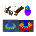
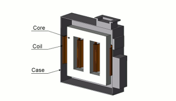 Fig. 1 A power transformer
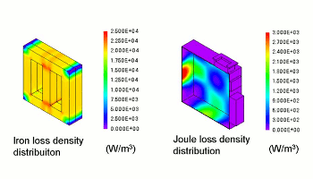 Fig. 2 Iron loss density distribution in the core and joule loss in the case
JMAG Application in Power Transformer Design
Surge countermeasures are often mentioned as one of the most important study items in power transformer design. It is especially important to estimate the effects on peripheral equipment from coil disconnection caused by a lightning strike or aging deterioration. Lightning resistant transformers themselves can withstand the high pressure from lightning, so their coils and insulating materials need to be studied to make sure that they have the correct arrangement.
In this section, we will first use JMAG to perform a surge voltage evaluation when a coil has disconnected in a three phase power transformer. After that, we will confirm whether the insulation between the coils in a lightning resistant transformer has been maintained during a lightning strike.
Evaluation of Surge Voltage from a Coil Disconnection
We can estimate the abnormal voltage that occurs when the W-phase coil ruptures in a three phase power transformer during steady operation by using the switch to cut off current flowing to the coil. This, in turn, makes it possible to simulate the rupture (Fig. 3).
Let’s use FEA to look at the voltage history that we have obtained for the coil (Fig. 4). We are using a 400 V sinusoidal wave as a power supply, but it is apparent from the voltage value at the moment of rupture that we need a pressure resistance of around 1240 V, including the equipment that connects to the surroundings.
JMAG needs a mere four minutes to obtain these results. Compared with a design based on traditional experience using a calculator, this makes it possible to obtain more accurate results faster.
Dielectric Strength Evaluation of a Lightning Resistant Transformer
The lightning resistance of a transformer’s main unit is as important to study as its surge voltage, and designs for lightning resistant transformers in particular have to be able to withstand high voltages. In this simulation, we assume that high voltage from lightning has been loaded to a transformer placed in insulating oil (Fig. 5, Table 1). Using FEA makes it possible to see the electric field distribution in the transformer, which will allow us to evaluate the arrangement of the coil and insulating materials, and examine whether or not the dielectric strength of each part is sufficient.
In this analysis, a voltage of 150 kV is loaded to the primary coil. Let’s take a look at the interior electric field distribution (Fig. 6). When we zoom in on the corner of the primary coil, we see that a maximum electric field of 9.05 kV/mm has occurred in the area. This is a local value that is hard to evaluate quantitatively in a design relying on traditional experience, but using FEA brings it to light. As a result, we find that the assumed dielectric strength of this analysis is less than 10 kV/mm.
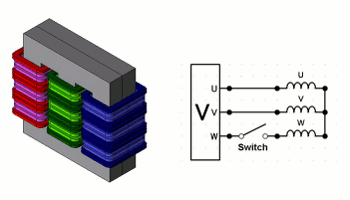 Fig. 3 A 3 phase power transformer model and its circuit
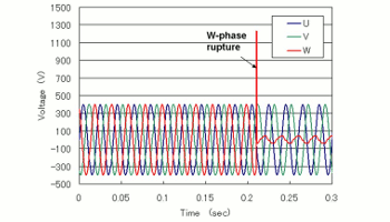 Fig. 4 The coil’s voltage history
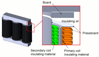 Fig. 5 Lightning resistant transformer
Table 1 Assumed dielectric strength in each part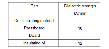
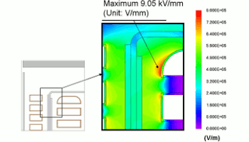 Fig. 6 Electric field distribution in the transformer
JMAG: Pursuing a Faster Transformer Analysis
Up to this point I have introduced the fact that, in addition to current and voltage, a transformer analysis allows you to visualize loss distribution and electric field distribution, which cannot be seen in actual measurements. At JMAG, we are developing technologies that allow you to obtain these results quickly.
I would like to introduce a few more details about the Time Period Explicit Error Correction method, which was used in the preceding section titled, “Evaluation of Surge Voltage from a Coil Disconnection.” In an analysis like this, when we skip the starting-up phenomena because the coil ruptures in a steady state, we want to shorten the transient phase to save analysis time. With JMAG, it is possible to eliminate this transient phase early on by using the Time Period Explicit Error Correction method (TP-EEC method). Using the TP-EEC method allows us to set the coil’s rupture time to 0.21 s (Fig. 7). This kind of cutting-edge technology makes it possible to reduce the analysis time to half of that required by traditional FEA. In the loss analysis that I mentioned in the introduction, the analysis time was shortened remarkably by using two features: The improved version of the A-phi method (A-phi Method 2), which can run a high speed analysis for eddy currents, and the SMP parallel computing function, which utilizes a multi-core machine effectively to improve analysis speed. JMAG also has technology that converges nonlinear iterations quickly.
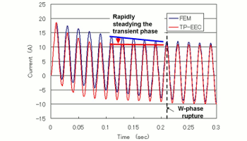 Fig. 7 Current history of the U-phase coil
In Conclusion
We used JMAG examine a power transformer design and perform an abnormal voltage evaluation during a coil rupture, which is a vital study item. We also shortened the analysis time by using the TP-EEC method to eliminate the transient phenomena that occurred in the analysis’s early stages. This allowed us to estimate the voltage increase during a coil rupture.
Additionally, we went through a dielectric strength evaluation of a lightning strike in a lightning resistant transformer. As a result, we found that the design proposal shown here can withstand a lightning strike of 150 kV. We were also able to confirm the electric field distribution in the transformer, which made it possible to study arrangements of a coil and insulating material that would have been difficult to examine using traditional methods.
I took the opportunity to introduce high-speed technology in JMAG that can be used in a transformer analysis, as well. Implementing the latest technology makes it possible to obtain analysis results in a shorter time than it would take with traditional FEA.
Visualizing phenomena in FEA gives veteran designers the ability to transfer their valuable techniques and knowledge to other designers and to the next generation.
JMAG’s cutting-edge technology allows you to estimate a product’s characteristics more easily and quickly than if you were using a traditional trial production. By all means, take this opportunity to begin using JMAG in your transformer design site.
(Kazuki Semba)
[JMAG Newsletter May, 2012]