The polygonal diagram of H. Görges (Das Görgessche Durchflutungspolygon) dates from 1907. Although it is highly developed in German literature, until recently it has been rare in English-language publications. Fig. 1 shows an example for a single-layer winding with 12 slots and 10 poles.
The Görges diagram is important in the theory of winding harmonics in induction machines and PM brushless machines. The torque in these machines is attributed to the fundamental space-harmonic, but the higher-order space-harmonics contribute to the harmonic or differential leakage inductance. It is sensitive to the winding configuration and the number of slots/pole, and in certain motors a high value is exploited to assist in flux-weakening and extend the speed range.
The Görges diagram provides a straightforward method for calculating this inductance. It is constructed from the sequence of MMF steps arising at each slot-opening in one traverse of the armature surface, drawn with the correct phase angle for the ampereconductors in every coil-side. The differential leakage coefficient is calculated from the root mean square radius of the polygon nodes, relative to the radius of the fundamental circle R which is computed from the periphery of the polygon and the fundamental winding factor. A projection in any direction gives the spatial distribution of MMF around the armature periphery at any instant, as shown in Fig. 1. We can see many properties at a glance, including even-order harmonics (if present).
The unusual example in Fig. 1 is a “collapsed” polygon with high harmonic leakage. For traditional machines with integral slots/pole, the polygon approaches the R-circle, giving a low harmonic leakage inductance.
The Görges diagram is a supreme example of the use of classical (yet elementary) mathematics combined with graphical representation, to resolve a complex phenomenon into a useful engineering formula. While the field theory of harmonic leakage is difficult to describe precisely in a practical way, the Görges diagram uses the simple concept of MMF steps to “tame the field monster”. However, it is now possible with finite-element analysis to re-examine the simplifying assumptions. Such effects as fringing and saturation modify the contribution of the higher-order harmonics, and they may lead to a reduction in the value of the harmonic leakage reactance.
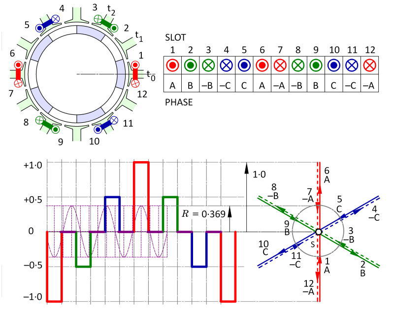 Fig. 1 Görges diagram for a single-layer winding with 12 slots and 10 poles