A space-vector — let us say, a space-vector of current — is a single complex number representing the combined effect of all three phase currents in an AC machine at a particular instant of time. The same statement can be made with respect to voltages or flux-linkages, and we are restricting our attention to 3-phase AC machines although the concept can readily be extended to AC machines with any number of phases.
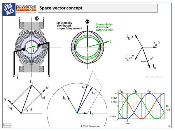
 Fig. 1 Space-vector definition and interpretation
The definition in boldface seems to be an extravagant claim. It suggests an almost magical quality in the idea that one single number (albeit a complex number) can represent everything one needs to know about the three phase currents in an AC machine. A more modest statement would be that it represents everything the control engineer needs to know in order to regulate or control the current in a field-oriented controller using a transistor PWM inverter.
From the point of view of the electric machine designer, the space-vector may seem rather exotic and even obscure. As designers we are accustomed to real voltages and currents, and although we often use phasors in the phasor diagram, the space-vector seems to belong outside that world. So let’s try to understand its properties in electric-machine language.
Here on the left we see a DC motor cross-section in which the main flux \( \Phi \) is established by the field poles in the vertical direction. We also see the armature current \( \mathbf{i} \) which flows through the rotor and establishes its own magnetic flux. The direction of this flux — the armature-reaction flux — is more or less orthogonal to the field flux. The pattern of ampere-conductors which establishes the armature-reaction flux has a fixed shape or spatial distribution, but once that distribution is given we can focus on just two parameters that define its main effects: the magnitude \( \mathbf{i} \) in amperes and the direction, which is determined by the angular position of the brushes. Even though the armature conductors are rotating, the direction or orientation of the pattern of ampere-conductors is actually fixed in space by the action of the commutator and brushes. By rotating the brushes we can alter the orientation of the armature current, and thus control its effects.
Even in the DC motor, it helps to resolve the current vector, if you will, into two components, one of which is aligned with the field poles and modifies the overall flux (and therefore also the terminal voltage), and the other one which is orthogonal to the field axis and controls the torque. Here we have the essence of field-oriented control, that is, the independent control of flux and torque; and it involves the resolution of a current vector into components which have a certain spatial orientation, especially in relation to the main field axis. The main field axis is distinct in some machines but not in others; but in all cases it is denoted as the d-axis or direct axis. Mathematically, the process of resolving the current (or more precisely the ampere-conductor distribution), into d- and q-axis components is a reference-frame transformation or mapping.
Now let us consider the stator winding of an AC machine, in which a sinusoidal spatial distribution of ampere-conductors sets up a sinusoidally distributed flux \( \Phi \). The important property of this flux distribution is its fundamental space-harmonic component, which has two key parameters, the magnitude \( \Phi \) and the direction. In the normal AC machine the flux \( \Phi \) is rotating at synchronous speed.
In comparing this with the field system of the DC machine, there are three obvious differences.
(a) First, in the DC machine the flux \( \Phi \) is stationary, but in the AC machine it rotates at synchronous speed. However, if we imagine ourselves to be an observer on the rotor, the flux will appear to be stationary and so we can dismiss this difference as a mere detail.
(b) Secondly, the field poles on the rotor of a synchronous machine are usually on the inside, whereas in the DC machine the field poles are on the outside. But for the purposes of our argument we can dismiss that too as an unimportant detail of topology, because what is important is the relative motion between the rotor and the stator, not which one is stationary and which one is rotating.
(c) Thirdly, the flux in a DC machine has a more-or-less rectangular spatial distribution around the armature, whereas in the AC machine we are concerned with the fundamental space-harmonic component which of course is sinusoidally distributed. The shapes of these distributions are of course vital in the design and operation of the respective machines, but for our purposes they do nothing more than to give rise to coefficients which appear in the performance equations, and then are seen no more.
Now if we have a sinusoidal distribution of ampere-conductors we can, in precisely the same way as in the DC motor, characterize its effectiveness by the same two parameters: the magnitude \( \mathbf{i} \) in amperes (give or take a coefficient which we have just mentioned), and the direction. Such a distribution represents the fundamental behaviour of the windings of an AC machine, and the two parameters (\( \mathbf{i} \) and the direction) are components of what we call a space-vector. We will see that there is a space-vector for each phase winding, and another space-vector that combines the effects of all three phases. In the induction motor we will find a similar set of space-vectors for the rotor as well.
In a typical AC machine with three phase windings, we have a space vector for phase a, one for phase b, and one for phase c. Each one of these is stationary in space, but its amplitude is proportional to the instantaneous current in the respective phase winding.
Now we can define the spatial directions in the so-called Argand diagram by means of three complex numbers: \( \mathbf{1} \) along the real axis, a at 120°, and a2 at 240°. Multiplying any complex number by a represents nothing more than a rotation of +120°. The complex numbers \( \mathbf{1} \), a, and a2 all have magnitude 1, and they define a three-phase frame of reference for the three phase currents and their effects along their respective phase-winding axes. That’s because the phase-winding axes are normally displaced 120° from one another in physical space around the bore of the stator. When we say 120°, of course we mean electrical degrees, so 120° means two-thirds of a pole-pitch, a pole-pitch being 180 electrical degrees and two pole-pitches 360 electrical degrees. We can also say that the complex numbers \( \mathbf{1} \), a, and a2 are themselves space-vectors, or unit space-vectors along the three winding axes.
Now if we simply add the three complex numbers representing the space-vectors of the individual phase currents, the result is itself a space-vector — another complex number \( \mathbf{i_s} \) — but the orientation of this one is not fixed: it depends, obviously, on the values of the three phase currents, as does its magnitude.
When the three phase currents follow a sinusoidal pattern as they do in steady-state operation, it turns out that \( \mathbf{i_s} \) is fixed in magnitude and rotates steadily at synchronous speed. Here we have the essence of the operation of the AC machine, at least in terms of one of its variables, the current — or more precisely, the fundamental space-harmonic of the ampere-conductor distribution. But the space-vector concept applies equally to the voltage, being defined from the three instantaneous phase voltages in exactly the same way that the space-vector of current is related to the three phase currents. Likewise there is a space-vector of flux-linkage, which is analogous to the flux \( \Phi \) in the DC machine.
We should note that there is a convention in which a scale factor of 2/3 is applied to the sum of the three phase space-vectors, in order to keep the peak value of the resulting space-vector equal to the peak value of the phase current in the steady state.
It should be easy to see that although this diagram is drawn in the ordinary complex plane, with the real axis along the x-axis and the imaginary axis along the y-axis, the space-vector \( \mathbf{i_s} \) can be further resolved along two orthogonal axes d and q. In this dq frame of reference, the components are \(i_{sd}\) and \(i_{sq}\), and they are written as real numbers. We could write them in boldface as complex numbers — space-vectors — but there is no need to do that because their orientation is implicit in that of the dq frame of reference which carries them.
Now we come to two important principles. First, we can observe that the orientation of the dq frame of reference is arbitrary. For example, in an induction motor, we can orient it in such a way that the d-axis is aligned with what is called the “rotor flux”, or more precisely, the space-vector of the flux-linkage of the rotor circuits. This orientation of the dq frame of reference is not the only one; different orientations lead to different architectures for the microelectronic controller, and this has proven to be important in the development of field-oriented control systems.
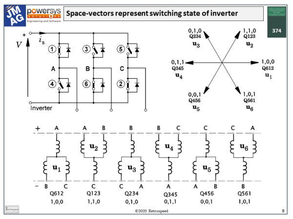
 Fig. 2 Space-vector modelling of the switching states of an inverter
The second principle is that the space-vector can be used to model the inverter. Fig. 2 shows an inverter circuit in which the transistors are modelled by plain single-pole switches, which are either open or closed, on or off. Normally in an AC sinewave inverter three transistors are on and three are off, and the particular combination defines the voltages at the three terminals of the motor. There are two additional states where all the uppers are on and all the lowers are off, and vice-versa, making a total of eight valid states. Each of these states defines a voltage space-vector at the motor terminals.
Thus we can say that the space vector unites the theory of the motor with that of the inverter, not only at the power-electronic switching frequency (usually a few kHz), but also the lower frequencies of voltage and current variations on a time-scale meaningful to the motor.
There is much more to the theory of space-vectors, and of course we don’t have enough space here to develop the subject. The learned-society journals are rich in reference material, and it is easy to find from the 1970s onwards. But I would like to finish with a humorous quotation from Professor Pupin writing in the comments on a well-known paper by Benjamin Lamme (1918) on the theory of the single-phase induction motor. In those days the august discussions were full of sardonic comments (and probably much laughter in spite of their earnestness and gravity). It is deliberately taken out of context, so please enjoy the humour, but don’t think badly of Professor Pupin, who I am sure would also share the humour if he were with us today:

![ミラー先生のモータ設計学び直しWEBセミナー [毎月更新]](/jp/wp-content/uploads/sites/5/engineers_diary/bn_prof.miller-150x150.png)


