 Fig. 1
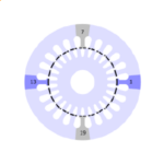
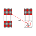
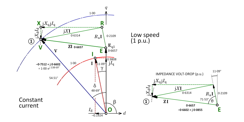
This article concerns the permanent-magnet brushless AC motor. We’re going to review the phasor diagram, which has been the basis of AC motor theory for about 120 years. We will consider two cases : low speed (Fig. 1) and high speed (Fig. 2). In the high-speed case we will see the effect of flux-weakening, and we will see how a control strategy could be devised for flux-weakening operation at high speed.
The phasor diagram starts with the open-circuit EMF OE. The symbols are the same ones used in [1]. All voltages and currents in the phasor diagram are r.m.s. values of fundamental time-harmonic components of the respective voltage and current waveforms (which may not be perfectly sinusoidal in practice). The EMF is drawn on the quadrature axis to reflect Faraday’s law, which in AC terms means that a flux-linkage phasor Ψ produces an EMF phasor jωΨ, where ω is the fundamental frequency in rad/sec. The open-circuit EMF is produced by the flux-linkage due to the magnet, and it is natural to set the flux-linkage phasor along the d-axis, in accordance with the long-established convention used with synchronous machines. jω then puts the EMF on the q-axis.
The current phasor OI is shown leading OE by the control angle ϒ. [Some engineers use β (= 90°+ϒ) as the control angle]. The current magnitude is 1⋅0 p.u. (per-unit). Note that when ϒ is positive, the current has a negative d-axis component, which is demagnetizing in the sense that it directly opposes the magnetomotive force of the magnet. In Fig. 1 Id = −0⋅1924 p.u., which is quite small. The q-axis component Iq = 0⋅9808 p.u., much larger. In nonsalient-pole (surface-magnet) motors, the torque is proportional to Iq and independent of Id, so it makes sense that Iq > Id, especially at low speed when the highest torques are usually required.
We now come to consider the AC voltage OV that is required to drive the current into the motor. This is the per-phase voltage at the terminals, or more precisely, its fundamental harmonic component. The actual voltage applied at the terminals by a PWM inverter is a very messy waveform that does not look anything like a sinewave, but the torque and the electromagnetic power conversion are entirely due to the fundamental time-harmonic components of voltage and current, so we can proceed with the phasor diagram and worry later about the relationship between the PWM inverter output voltage and its fundamental harmonic component; (see [1], p. 404).
The voltage OV must exeed the open-circuit EMF OE by the phasor EV, which is the voltage-drop created in the armature impedance Z by the current I. The old-fashioned term for the reactive part of this voltage-drop is armature reaction: the stator winding is the armature and the voltage-drop is reactive, because it is associated with flux-linkages established by the current. Sometimes these flux-linkages are plotted in a separate vector diagram, but this is not really necessary and we don’t need to do it here.
The voltage-drop EV has a resistive component ER which is simply the product of the armature (stator) resistance and the current phasor. This phasor is always parallel to the current phasor. In Fig. 1 its magnitude is 0⋅2109 p.u., which is very high for most PM motors, but at least it makes for a clear phasor diagram. (Such a small value would be found only in very small motors).
The reactive component RV is split into two components, RX and XV. RX = jXqIq is the voltage-drop in the q-axis synchronous reactance Xq, while XV = jXdId is the voltage-drop in the d-axis synchronous reactance. Note that there is no cross-coupling in this simple representation: in other words, Iq produces no voltage in the d-axis and Id produces no voltage in the q-axis. There have been heated debates over the years, as to whether this is acceptable, since under saturated conditions there is often cross-coupling between the two axes. However, it is always possible to find “saturated, cross-coupled” values of Xd and Xq at any operating point, and therefore it is always possible to draw the phasor diagram in the form shown here. The finite-element method is essential for this calculation, but the method of using it to determine the necessary reactances is not unique, and in any case it is outside the scope of this article.
In a nonsalient-pole (surface-magnet) motor Xd = Xq and the reactive voltage drop RV always leads the current phasor by exactly 90°. In this case we could dispense with the separate phasors RX and XV, and simply use RV = jXI, where X = Xd = Xq. However, it is better to keep the separate components. Why? For one thing, the diagram is clearer with them than without them, especially when it has to be related to the field-oriented control used in the PWM inverter. It would be better to dispense with the RV phasor. We usually do, and we lose nothing!
A second reason for retaining the separate components is that the same diagram applies to the salient-pole machine (such as the interior PM motor or IPM), in which Xd and Xq are unequal and the phasors OI and RV are no longer orthogonal. In fact the same diagram applies also to the wound-field AC machine, the main difference being that the open-circuit EMF is variable and controlled by the field current. The diagram in this form is essentially the two-reaction diagram of André Blondel [about 1895], and it was widely used in design and analysis of machines for more than 30 years before Park’s transform brought a more formal mathematical approach [1929]. It can even be argued that Park’s transform made matters unnecessarily complicated, and set the education of electrical engineering students along a much more mathematical and less intuitive path.
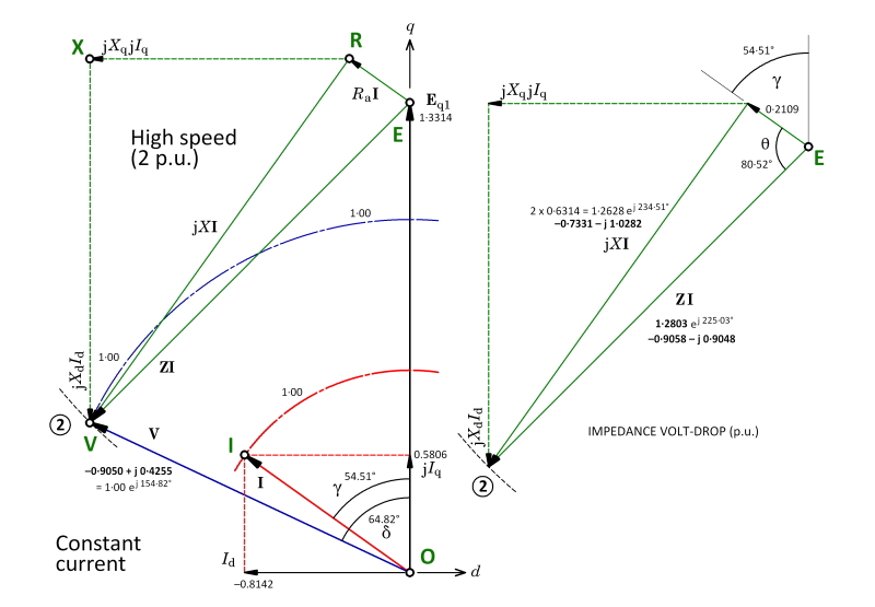 Fig. 2
Ironically, today with the finite-element method (which is intensely mathematical behind the scenes), we can bring Blondel’s genius back into the limelight with a brilliant combination of accurate results and clear physical insight.
Let us leave this historical digression and proceed to Fig. 2, which shows the phasor diagram at twice the speed. First, however, notice in Fig. 1 that we conveniently arranged matters so that the terminal voltage OV came out with a value of 1⋅0 p.u. This is not accidental. What it means is that at the speed at which Fig. 1 is drawn, and at the particular value of current and control angle, we have chosen the base voltage so that the per-unit terminal voltage is 1, or 100%. In practical terms what we’re saying is that when we operate this motor at the speed and load represented by Fig. 1, we require a definite AC fundamental voltage from the inverter and we’re going to define this as 1⋅0 p.u. Then at other speeds and loads, we can express the required voltage relative to this operating condition.
But in Fig. 2, as if by magic, we find that the voltage OV is again equal to 1⋅0 p.u. This also is not accidental. What we’ve done is this : we have doubled the speed, kept the same current magnitude (which we’ve defined as 1⋅0 p.u.), and advanced the control angle ϒ so that the terminal voltage does not exceed 1⋅0 p.u.
It should be obvious from Fig. 2 that the voltage-drop phasor EV is much bigger, but the XV component is much bigger, and this is what rotates the EV phasor round in the anti-clockwise (positive) direction until its tip V lies on the circular voltage locus with radius 1⋅0 p.u. The negative (demagnetizing) current component Id is increased by more than four times, to −0⋅8142 p.u.
The reactive voltage-drop RX = jXqIq isn’t helping. It is tending to push the tip X out to the left, further from the 1⋅0 p.u. voltage circle. Even though Iq is only 59⋅2% of the value it had in Fig. 1, the reactance Xq has doubled, so RX has increased by the factor 1⋅184.
At the end of the EV phasor in both diagrams, there is a short arc drawn with a dashed curve. This expresses the search for the value of the control angle required to swing the EV phasor so that its tip sits on the voltage-limit circle. For example, when we double the speed, we assume that Xd, Xq and the EMF all increase by a factor of 2⋅0. With the same current magnitude, we can draw the voltage-drop diagram on the right-hand side; this is just the impedance triangle multiplied by the (complex) current phasor, which gives it the correct orientation to be transferred to the main phasor diagram on the left. Initially the control angle is unknown, but this triangle has a fixed shape and size. Therefore all that is needed is to rotate it about the point E until the tip V sits on the voltage-limit circle.
With fixed values of Xd and Xq, this process can be performed with a simple closed-form solution for the control angle. However, in practice it is more complicated because Xd and Xq are both variable as a result of saturation (and even the resistance Ra varies with temperature, although its effect is often small). Therefore it is necessary to use finite-element calculations to update Xd and Xq in an iterative process which searches for the requisite value of control angle ϒ.
Indeed in practice, control strategies may vary the current magnitude as well as the control angle, depending on the performance requirements. For example, it is sometimes desirable to maintain constant power at high speed, not constant current. In the example shown in Figs. 1 and 2, the machine has no saliency and the torque is proportional to Iq. We can see that it decreases in the ratio 0⋅5806/0⋅9808 = 0⋅592. While the speed has doubled, the power has actually increased in the ratio 2 × 0⋅592 = 1⋅184.
Also note that in finite-element calculations, the induced voltage can be calculated directly from the fundamental space-harmonic component of the actual airgap flux, which includes the effect of the current as well as the magnet, and takes saturation fully into account. The resistive voltage-drop is missing from this calculation but is easily added. This might seem to imply that we don’t really need Blondel (or Park, for that matter). However, without them, how would we talk to the control engineers? Park’s transform is needed to define Id and Iq to the finite-element method, which works with actual phase currents, and it is also needed to extract the d– and q-axis flux-linkages from the phase flux-linkages. However, what is not needed is the intricate theory of inductance and the complicated diagonalisation of the inductance matrix from (a,b,c) coordinates to (d,q,0) coordinates, which is given in so many textbooks and yet which becomes unreliable under saturated conditions. It is better to use the finite-element method to handle all relationships between flux-linkage and current, while still retaining Park’s transform and its inverse to express these variables in the two coordinate systems. As to whether or not we need Blondel, there seems to be no question: the visualization obtained from phasor diagram would surely be much less clear without the two-axis representation.
[1] Design of Brushless Permanent-Magnet Machines, by J.R. Hendershot and T.J.E. Miller, Motor Design Books, LLC, 2010. Available in Japanese from MS-TECH, Tokyo.
