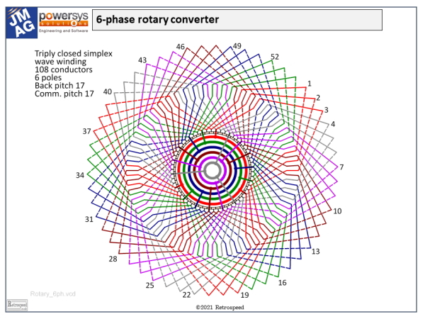
 Fig. 1
In electrical machine theory we often hear the term rotational EMF. What exactly does it mean?
“EMF” means “electro-motive force”. In electrical machine theory it is a voltage induced in a closed circuit by the rate of change of flux-linkage ψ. It always obeys Faraday’s law:

If the sign conventions of voltage and current are chosen to define the circuit as a source of electrical power, a negative sign is added; but if they are chosen to define the circuit as a sink of power, the negative sign is not required. In both cases, however, the polarity of the EMF is such as to tend to drive a current in such a direction as to oppose the change in flux-linkage, and this principle is known as Lenz’ law.
In the design of electric machines there are several standard formulas for the generated EMF. They differ according to the type of machine and the waveform of the EMF, but they are all derived from eqn. (1). Eqn. (1) is not in a convenient form for classical design calculations, but in its discrete form it is common in finite-element computations.
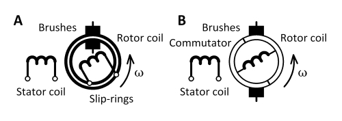 Fig. 2
In Fig. 2 let us consider a simple machine with a stator coil and a rotor coil. Assume that the stator coil carries direct current which establishes a flux that links the rotor coil. The flux-linkage of the rotor coil will vary in a cyclic manner and it will alternate between positive and negative values, with one positive maximum and one negative maximum in each rotation. The changing flux-linkage generates an EMF according to eqn. (1).
In case (A), the rotor EMF is communicated to the stationary “outside world” by slip-rings and brushes without modification, so the voltage across the brushes is AC.
In case (B) the rotor EMF is communicated to the stationary “outside world” by a commutator and brushes. It is evident that the commutator rectifies the alternating EMF by reversing the connections of the rotor coil twice in every rotation, so the voltage across the brushes is DC. It is more correct to say that it has a non-zero average value, while it also contains a significant ripple component. The non-zero average value is the so-called DC component.
Now let us return to eqn. (1) and consider the fact that the flux-linkage of a coil may vary either as a result of its rotation, or as a result of the variation of the magnetic field. These two distinct effects can be expressed mathematically by partial differentiation, writing

The first term is attributed to rotation, while the second term is attributed to the variation of the flux. The first term is called the rotational EMF, and it is proportional to the instantaneous angular velocity dθ/dt. The second term is sometimes called the transformer EMF. Both of them are induced EMFs.
If the flux is constant, the transformer EMF vanishes, leaving the rotational EMF. If the flux is constant the EMF in the stator coil will be zero. Only the rotor coil will have an EMF, and as we have seen this can be communicated to the “outside world” either by slip-rings and brushes, or by commutator and brushes. The rotational EMF can therefore be AC or DC.
Electromechanical power conversion arises from the interaction of the rotational EMF with the current at the brushes. In both cases A and B in Fig. 2, this current would traditionally be called the armature current; the current in the stator coil is the field current, whose sole purpose is to establish the flux. It plays no direct part in the power conversion.
Fig. 2 can thus be taken as the basis for both AC machines (A) and DC machines (B), although in practice many more coils are required in both cases. In the AC machine the field must be made to rotate, and the common way to achieve that is to exchange the stator and rotor coils in Fig. 2, providing the rotor with DC through slip-rings; then the stator has a multiple of 3 coils to generate EMFs in three phases. In the induction motor the rotating field is established by AC in a polyphase stator, and the rotor rotates asynchronously with this field; no separate field winding is necessary, and the rotor circuit may be short-circuited so that no connections are required to the stationary “outside world”.
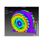
The rotary converter (Fig. 1) is a historic machine having DC field coils on the stator and a rotor with a large number of coils connected in series in a continuous wave winding. These coils are connected sequentially to the segments of a 54-segment commutator, but they are also connected in groups of 3 to a set of six slip-rings which collect a 6-phase AC voltage. Both the commutator and the slip-rings have their own separate brush-sets, but one brush-set carries DC while the other carries AC. On the rotor, the DC and AC currents in each conductor are one and the same, while the accumulated voltages at the brushes are AC at the slip-ring brushes and DC at the commutator brushes. Neglecting losses, the AC power is equal to the DC power, and the machine converts AC to DC (or vice-versa) by itself with no external prime-mover. (A small auxiliary machine may be mounted on the same shaft for starting purposes, but this does not participate in the main power-conversion).
Isn’t it a little bit crazy — even a waste of time — to be thinking about a machine that disappeared long ago? If you’re interested only in current practice (including power electronic frequency-conversion) and you don’t need to consider the principles of EMF generation in electric machines, then maybe it is a waste of time. But if we take a slightly wider view, the rotary converter gives us a beautiful example of the essential meaning of rotational EMF. By contemplating it, we might hope to have a clearer physical visualization of rotational EMF.
It is also a fascinating player in the history of electrical power engineering. In the early days it was quickly realized that AC was superior for generation and especially for transmission over any distance beyond a few kilometres, mainly because DC was limited to lower voltages and the cost of high-current cables quickly became prohibitive. But railways and tram systems were needed over longer and longer distances, so the rotary converter was developed to convert AC to DC at the point of use, after transmission from remote power stations by AC. This pattern of conversion has not changed even in modern times, except insofar as the DC traction motor has given way to the AC traction motor. This does not actually simplify the system : on the contrary, it introduces an additional frequency-converter with variable frequency and variable voltage at the terminals of every traction motor. In these systems all the frequency-conversion stages are accomplished, of course, by static power-electronic converters. The rotational EMFs which we can see so clearly in the rotary converter are still there: it’s just that they are buried in the space-vector control theory of the converters.

