 Fig. 1
Every type of electric motor has certain essential features. One way to begin to understand them is to make a drawing, and at the same time make a list of observed features and characteristics. I would say it is a good exercise for students as well as for experienced engineers, because it leads directly to thinking about design and manufacture, and the performance characteristics, without the need for any equations or software. We spend a lot of time with equations and software, trying to exercise a kind of numerical control over known features and characteristics, rather than sitting down and wondering where these features and characteristics actually come from. As we imagine them and list them and describe them, it’s a good idea to be mild and understated in our evaluations, and not to take extreme positions or to be too critical. They are just features and characteristics of a useful and effective product, not bullet-points to destroy a competitor’s creativity or to vaunt one’s own product unreasonably.
Let’s start with the name. Some people have difficulty with the name because they argue that “reluctance” cannot be “switched”. This misses the point, because it is the current that is switched, not the reluctance. The alternative name “variable reluctance motor” was proposed, but that fails to distinguish between the switched reluctance motor and the synchronous reluctance motor, which is a completely different machine. The term switched reluctance motor was first used by Professor S.A. Nasar of the University of Kentucky in 1969, but it became firmly established through the work of S.R. Drives Ltd. (now part of Nidec) in the 1980s. The term electronically-commutated reluctance motor was used for a time by the Pacific Scientific company, abbreviated to ECR, and this could be argued to be the most elegant and accurate name, but switched reluctance is now so widely used that alternatives might cause confusion. Nevertheless, the notion of commutation is appropriate because the current is switched in DC pulses synchronized with the rotor position. (The current in the inverter-fed synchronous reluctance motor could also be said to be commutated, but only at the carrier-frequency of the inverter; its basic waveform is sinusoidal, not pulses of DC).
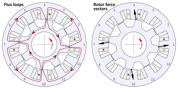
The most important essential features of the switched reluctance motor are that it has no magnets and no rotor windings. In Fig. 1 we can see a common embodiment with 12 stator poles and 8 rotor poles. In many other types of motor we would call them teeth rather than poles. They are called poles because the entire flux per pole passes through one stator pole and one rotor pole in a single crossing of the airgap, during the interval of torque production. This is also the case in brushless permanent-magnet motors wound with single-tooth coils, but there the poles are associated with the magnets and the distinction between teeth and poles does not really arise. We often speak of a PM motor with 12 slots and 8 poles as having 1⋅5 slots/pole; but it would be rare to hear the term “teeth per pole”. In the switched reluctance motor the rotor teeth take on the role of the magnets: they are magnetized by induction as they pass the relevant magnetized stator teeth. Yes, they are teeth, but they are doing the job of poles.
The 12/8 motor has three phases as indicated by the red, green, and blue coils. Our discussion refers to the operation of the red phase only; thus we can ignore the other two phases (although in practice the phases do interfere with one another slightly, because of shared sections of the magnetic circuit). The coil-sides are shown hatched, and they are dimensioned in such a way that the coils can be pre-wound and slipped over the teeth (I’m sorry — poles), without touching the adjacent coils. From early days, this notion was promoted as one of the advantages of the switched reluctance motor — it wasn’t necessary to have complicated shed-winders or overlapping coils with the attendant difficulties of insertion. And it would be so easy “in the field” to replace a burnt-out coil! Just imagine road-side repairs to an EV with switched reluctance wheel motors — almost as easy as fixing a flat tyre. However, if the coil-sides are shaped to conform to this property there will be a significant empty space, more or less triangular in shape, between the coils. We can see this in Fig. 1. This a waste of precious cross-sectional area; and it’s quite a serious one, because the switched reluctance motor requires a high electric loading (a lot of ampere-conductors) to get the best out of it.
The rotor is shown at a position where the torque produced by the red phase is close to its maximum value, and is directed in the anti-clockwise direction. The mechanism of torque production is the principle of a variable-reluctance actuator, in which the torque tends to move the rotor to a position of maximum inductance. This position is reached when the active rotor and stator poles become aligned. At that point the torque is zero, and if the rotor moves past the aligned position the torque will change sign, regardless of the direction of the current. This alone makes it clear why the current in the active phase must be switched off as quickly as possible once the aligned position has been reached; in practice, it must be switched off (commutated) slightly before this position, to allow time for the flux-linkage to be returned to zero.
The left-hand diagram shows the general conformation of the magnetic field in terms of four flux-loops corresponding to the four magnetic poles arising in the 12/8 three-phase motor. It is clear that there is a severe constriction of the magnetic circuit in the region of the partially-overlapped poles. The flux per pole is not constant but is still increasing at this position, having been “switched on” a few degrees before the poles begin to overlap. But it is generally sufficient to cause heavy saturation of the corners of the partially-overlapped poles. This constriction of the magnetic circuit, and the saturation which comes with it, is an essential feature of the switched reluctance motor. No such constriction could be imagined in any kind of AC or DC motor, where the flux per pole flows through a magnetic circuit with an unvarying cross-section, and where saturation is a parasitic second-order effect. In the switched-reluctance motor the saturation of the pole-corners actually helps to level the torque waveform, because it tends to provide a steady rate of change of flux-linkage as the overlap increases, and this can be said to generate a more-or-less constant back-EMF against which a flat-topped current produces a flat-topped pulse of torque.
Not only that, but the pole-corner saturation affects the overall energy-conversion process in each cycle or stroke of operation, reducing the volt-amperes required from the power electronic drive per kilowatt of electromechanical power conversion. This counter-intuitive characteristic caused much consternation in the early days of the switched reluctance motor, engendering heated debates about whether saturation could ever be beneficial. The short summary of this is that while saturation does indeed reduce the “volt-amperes of silicon” per kilowatt of power conversion, (more or less to a level comparable with the induction motor), it also reduces the power conversion available from a given motor volume by a much larger factor. It is emphasized that this particular saturation effect arises from the concentrated zones of saturation at the overlapping pole-corners; any saturation further up the poles, or in the yokes, is purely deleterious and serves only to limit the overall power conversion per unit volume. This is one of the reasons for tapering both the stator and rotor poles — to concentrate the effects of saturation at the overlapping corners.
The black arrows in the right-hand diagram represent the electromagnetic force vectors on the rotor poles at the position shown. Consider their orientation. They have a strong radial component and a weak tangential component. The tangential components combine to produce the working torque, while the radial components cancel so that there is no net radial force on the rotor (considered as a rigid body with no eccentricity or asymmetry). Both components are, of course, present in all motors, and it is always the case that the radial component is much bigger than the tangential component. In conventional AC and DC motors, however, the distribution of both components is much more gradual, whereas in the switched reluctance motor it is highly concentrated over the narrow zones where the active poles are coming into alignment. Not only that, but the mechanical stiffnesses of the stator and rotor of a switched reluctance motor are inherently less than in a conventional AC or DC motor, because of the narrow cross-sections of all parts of the magnetic circuit. We must expect to have to deal with acoustic noise arising from the resulting vibratory distortions of the structure.
While all these features of the switched reluctance motor are distinctive, some of them may appear problematic and it is easy to fall into the trap of dismissing it without further consideration. A similar fate could be said to have overtaken the DC motor, whose chief “essential feature” was (and still is) the commutator and brushes. Did that prevent the DC motor from dominating the field of industrial drives for nearly a century, or render it obsolete in the face of competition from inverter-fed motors? In some applications yes; in others, no. The implication for the switched reluctance motor is not whether we should use it, but when we should use it.
The answer to this question can be answered more fully by reviewing the many successful applications of the switched reluctance motor. An understanding of essential engineering features (such as those discussed here) is not sufficient by itself, because there are so many other factors involved in applications and product development. But of course it’s a fact that application opportunities arise from the essential engineering features.
Reference : Electronic Control of Switched Reluctance Machines, Newnes Power Engineering Series, Oxford, 2001. ISBN 0 7506 50737


