 Fig. 1
Torque ripple is the variation in the torque of an electric machine as the rotor rotates. It depends on many factors including the current waveform, but in permanent-magnet motors the component known as cogging torque is usually defined for open-circuit conditions. It is attributed to the interaction of the magnets with the slotting of the stator. We have all seen polished examples of brushless motor products on the stands at trade shows, and the temptation is to turn the rotor by hand to try to feel the cogging torque. Of course that is not a reliable test, because the running torque ripple may be much greater than the cogging torque when the motor is excited. A contrasting example can be found in the switched reluctance motor, which has no magnets and therefore no cogging torque; but its running torque may have a certain amount of ripple.
Cogging torque arises also in induction motors. It is classified as a parasitic synchronous torque, as distinct from the harmonic asynchronous torques (of which the running torque is the main or fundamental component). In particular it can cause locking at standstill, so that the motor will not start. Other synchronous torques may cause the motor to run at a fraction of synchronous speed, and this effect is exploited productively in the vernier motor [Lee, 1963]. In induction motors the cogging torque is always a “vernier” effect because the numbers of stator and rotor slots are generally not in an integer ratio, and the rotor is synchronizing with a harmonic permeance wave which has more to do with the difference between the slot numbers than with their ratio. In permanent-magnet brushless motors the cogging torque is a synchronous effect locked to the rotor, which experiences a modulation of the total magnetic circuit permeance as it rotates past the stator slot-openings. The cogging-torque period is related to the ratio of the number of stator slots and the number of poles. For example with a 12-slot stator, the cogging-torque period is equal to 1.0 times the stator slot-pitch with 4 poles, 0.5 times with 8 poles, 0.2 times with 10 poles, and 0.1429 with 14 poles. These values determine not only the amount of skew required to eliminate the cogging, but they are also related to the amplitude of the cogging torque, which tends to decrease as the ratio slots/poles becomes closer to 1.
The calculation of the cogging effect is obviously important in the motor design. Because it depends on fine details of the geometry in the airgap region, the finite-element method is essential. Even so, accurate calculation is quite challenging especially in induction motors where the air-gap is extremely narrow compared to the rotor diameter. One obvious approach, commonly used, is to compute the Maxwell stress around the air-gap. Plotted as a waveform of torque versus rotor position, the result of this calculation tends to be noisy because of the discretization inherent in the numerical analysis process. We can say that the “noise” is amplified by the fact that the torque is a derivative of coenergy with respect to rotor position, and differentiation tends to amplify noise.
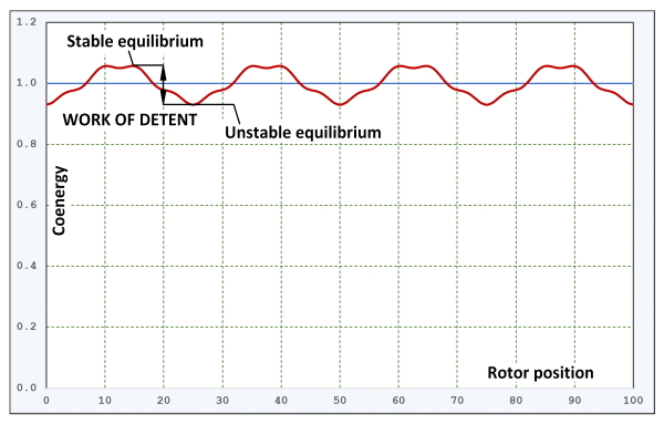
If instead of calculating the torque we calculate the coenergy, we can expect a smoother waveform such as the one shown in Fig. 1. Of course if we differentiate this with respect to rotor position, the discretization noise will re-appear. But is it really necessary to differentiate it, and is it really necessary to consider the torque at all?
To answer this, it may be of interest to borrow from the theory of stepper motors, in which synchronous locking is not a parasitic effect but is the main mode of operation. A stepper motor generally moves to a certain position and holds that position against whatever disturbing torques may be applied to it. The holding torque is sometimes called detent torque. In my dictionary, “detent” means “a stop or catch in a machine which prevents motion”, but in the electric machine the “mechanism” is that of electromagnetic forces.
Now consider a graph of magnetic coenergy versus rotor position, as in Fig. 1, plotted over four cogging-torque cycles in this example. A stable detent position corresponds to a maximum coenergy, while an unstable position corresponds to a minimum. (The opposite is true of the stored field energy). This can be explained more easily if we differentiate the waveform and plot the torque. At the detent positions the torque is zero, but its gradient is positive at unstable detent positions, and negative at stable detent positions. What this means is that if we displace the rotor slightly from a stable detent position, it will exert a restoring torque tending to bring it back to the detent position. But if we displace it slightly from a unstable detent position, it produces a torque in the same direction and it will tend to keep going until it reaches the next (neighbouring) stable detent position. Stepper-motor engineers are very concerned about the stability of the detent positions.
An unstable detent position can be described as the point at which the rotor is free from the “field” of the next or previous stable detent. To move the rotor from a stable detent to such a “free” position, work must be exerted equal to the difference in coenergy between the two positions. This is, of course, the integral of the torque over the angle of displacement. (This principle assumes constant MMF excitation, which makes the torque equal to the derivative of coenergy with respect to position. In permanent magnet motors the MMF is the coercive MMF of the magnets, with no current flowing in the windings).
So we come to the concept of “work of detent”, as shown in Fig. 1. This is a direct measure of the cogging effect. It is very simple. It is devoid of the complex harmonics we often see in the cogging-torque waveform, and in fact it represents the work we must do with our fingers and thumbs when testing those gleaming brushless PM motors on the stands at the trade shows.
If you are confident enough to discern correctly any two rotor positions corresponding to a stable and an unstable detent, the coenergy need be calculated only at these two positions. This gives rise to a fantastically quick way to evaluate the cogging, without having to calculate the cogging-torque waveform which is inherently a slow process requiring rotation of the rotor. Just a word of caution, however : Fig. 1 is drawn with an exaggerated variation in the coenergy. In a well-designed motor (that is, one with very low cogging), the variation is extremely small, so the calculation must be done accurately.
In Fig. 1 the horizontal axis of “rotor position” has been drawn deliberately with no particular units. We can see four cycles, so for example with a 12-slot 10-pole brushless PM motor we would expect 100 to correspond to 4/5 × one stator slot-pitch. In an induction motor we might expect it to correspond to four rotor slot-pitches, because the excitation would be on the stator. However, if there are common factors (multiples) between the numbers of stator and rotor slots, the cogging period may be a fraction of one rotor slot-pitch. The periodicity is important in both types of motors, because it
helps to determine the required amount of skew.
The method of calculating the work of detent was developed recently in connection with a standstill lockup problem with an induction motor having a stator/rotor slot combination outside the recommended norms. An interesting side-product of the coenergy calculation is the average value of coenergy, which is an indication of the “inductivity” of the motor, somehow encompassing both the leakage and the magnetizing inductances. Changes in the slot geometry intended to reduce the cogging detent can be ranked according to their effect on the “inductivity”. Since the breakdown torque of induction motors is inversely proportional to the leakage inductance, the average coenergy proves useful in this ranking process.
As far as I know, the subject of cogging and torque ripple in brushless PM motors has had much analysis in recent years, but one might ask if the subject of cogging torques in induction motors is due for reappraisal in the light of calculations such as these, in which finite-element methods provide powerful insight as well as accurate data. Much of the theory of harmonic effects in induction motors is relatively old, and such a study might produce interesting results. A good topic, perhaps, for one or more Ph.D. projects.
References
W.K. Koch, Discussion to Lee C.H., Vernier Motor and Its Design, IEEE Transactions on Power Apparatus and Systems, 82 (66), pp. 343-349, 1963.
Harris M.R., Andjargholi V., Lawrenson P.J. and Hughes A., Unifying approach to the static torque of stepping-motor structures, Proc. IEE, Vol. 124, No. 12, 1977, pp. 1215-1224.
Harris M.R., Hughes A. and Lawrenson P.J., Static torque production in saturated doubly-salient machines, Proc. IEE, Vol. 122, No. 10, 1975, pp. 1121-1127


