 Fig. 1
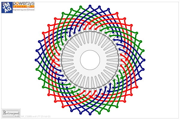
In Column 34 we deduced several inherent features of the synchronous reluctance motor merely by inspecting its cross-section and considering the main flux-paths, and here we will do the same for the induction motor, Fig. 1. In order to encourage close inspection of the drawing, and to practise the common terminology, Fig. 1 is presented without labels.
Beginning with the stator — wait a minute, what is the ”stator“? It’s the stationary or static part, just as the rotor is the rotating part. In Fig. 1 the stator is on the outside and the rotor on the inside, (but there are a few instances of induction motors in which the rotor is on the outside and the stator on the inside). The rotor and stator are essentially cylindrical and they are separated by an air-gap which in Fig. 1 is clearly very small compared to the diameter of the rotor.
Let us look at the stator. We can see the coloured end-windings which join the coil-sides between two slots. The coil-sides running along the slots are visible only as dots. There are 36 slots, and every coil has a span of 8 slots or 8 slot-pitches. Since there are 36 coils, each with two coil-sides, there are 2 coil-sides in every slot, and this is called a 2-layer winding. In this case one coil-side is in the bottom of a slot, and the other in the top of another slot. How this is achieved is one of the marvels of electric motor manufacturing. There are several ways, and one of the most elegant which we see nowadays in automotive traction motors is the hair-pin winding. Search ”hair-pin winding in electric motors“ on the internet, and you’ll see many splendid examples.
The coils are laid in groups of three : red, red, red, then blue, blue, blue, then green, green, green; and this pattern repeats four times over 360°, going in the counter-clockwise direction. The colours denote the three phases UVW, and if we assign U=Red, V=Green, W=Blue we would label the complete winding (going in the counter-clockwise direction):
UUU WWW VVV UUU WWW VVV UUU WWW VVV UUU WWW VVV
The order is important! In a 3-phase machine the spatial order of the phase windings determines the direction of rotation, and if the three sinusoidal phase currents are in their normal phase sequence UVW in time, it would seem that our winding sequence is back-to-front : UWV instead of UVW. Should the order not be UVW, going in the counter-clockwise direction?
To understand this a little better, we need to look at the number of poles.
The number of poles isn’t obvious in an induction motor. There are no magnets or field windings to be counted. The rotor has 30 slots, but surely the number of poles is not 30. And it certainly is not 15 (30/2). In any case, nothing is connected to the rotor, so it could not possibly define the number of poles. So what defines the number of poles?
The stator winding defines the number of poles. The key feature to look for is the number of coil-groups in one phase, let’s say, the red phase U. The coils are laid in groups of three, and there are four groups. That means four poles.
If we have 4 poles, the pole-pitch is 360°/4 = 90°. That corresponds to 9 slot-pitches exactly. We call this the number of slots per pole. Since this is an integer, we refer to the stator as an integral-slot stator.
Now we have already noted that each coil spans 8 slots, not 9. We say that the coils are short-pitched or chorded. (A coil spanning 9 slots would be a full-pitch coil). Also, the three coils belonging to one group are spread out or distributed over a definite angle, and the number of slots per pole per phase is 9/3 = 3. The definite angle of spread is 3 slot-pitches, and its value in Fig. 1 is 3 × 360/36 = 30°. This angle defines what we call a phase belt, and we can identify a phase belt by counting 3 red coil-sides together at the stator bore, and taking the angle between the centre-lines of the teeth on either side of this group, that is 3 slot-pitches or 30°. It’s important to understand the phase-belt angle as three slot-pitches, and not two (which is what we might think if we ”hop“ from a first red coil-side to a third red coil-side).
Now let’s have a little think. You can close your eyes for this bit : it might help. Let’s ask ourselves the question: how far would we expect the rotor to rotate in one cycle of the AC supply frequency? The logical answer, surely, is two pole-pitches. That would mean, surely, that everything in the machine would look exactly the same — all the alignments, all the symmetries, all the details of the drawing, and the flux pattern and the ampere-conductor distribution would be reproduced precisely after a rotation of two pole-pitches. And after another rotation of two pole-pitches, and another, the drawing would look precisely the same.
This is an intuitive explanation of what we call the synchronous speed. It is the number of cyles per second multiplied by the number of pole-pairs, or ƒp rev/sec where ƒ is the frequency and p is the number of pole-pairs. It is the speed at which the flux pattern and the ampere-conductor distribution rotate. Why pole-pairs and not poles? The poles come in pairs (NS), and a complete spatial cycle spans two pole-pitches. In one complete cycle of the AC frequency the rotation at synchronous speed will cover 360/p degrees, and it will cover a complete revolution in p cycles of the supply frequency.
Now let’s suppose we want the motor in Fig. 1 to rotate in the counter-clockwise direction, and let’s suppose the phase sequence is UVW or red, green, blue. The current in the green phase V will reach a peak value one-third of a cycle in time after the peak in the red phase U. In one-third of a cycle the rotation at synchronous speed will cover 1/3 × 360°/p, and since 2p = 4 (defined by our winding), we have p = 2 and so this rotation is 120/p = 60°.
So in order to rotate in the counter-clockwise direction we expect to find the green phase (V) located 60° round from the red phase (U), going in the counter-clockwise direction. At this point I will ask you, dear reader, to inspect Fig. 1 and convince yourself that the green phase is exactly where it should be. As a hint, start with any coil of the red phase, and count 60° or 6 slot-pitches in the counter-clockwise direction. You should find a coil belonging to the green phase, and this coil should be in the same positional relationship relative to the other coils of the green phase, as the red starting coil was to the other coils of the red phase.
This is an important exercise. I would say that the student must work this out in his or her own mind — and of course, come up with the same answer as the professor! I do hope I haven’t made a mistake in the drawing. I’m pretty sure it is OK. If not, someone will write to me (I hope). But the words may be harder to follow than the diagram. It’s important to get these basic notions clear in one’s mind, and it has to be said that many textbooks start at a rather academic or abstract level, assuming that the reader already has these concepts. Best of all, visit a winding shop or a winding-repair shop, and ask the technicians how they decide the order of the phases, in relation to the required direction of rotation.
The terminology is also important, so that we can discuss the whole business with one another. Maybe I should have put labels on the diagram, to avoid misunderstanding. If I had put labels, it might look as though the diagram were completely self-explanatory. But it isn’t. Like so many engineering diagrams, it requires interpretation and imagination on the part of the reader. I hope I’m not dodging my duty as a teacher. On the contary, a good teacher should surely set exercises! Easy ones? Maybe, maybe not.
Next time we’ll start to get a grip on the actual working of the induction motor. If you think about it, we have so far discussed only the winding, and this winding could work just as well with a synchronous motor such as an IPM or a wound-field motor. In the synchronous motor the rotor rotates in step with the rotating flux-pattern and ampere-conductor distribution at synchronous speed. But not in the induction motor.
Please note that all the angles in this article are in mechanical degrees (not electrical degrees). The 30° phase-belt is a 60° phase-belt in electrical degrees, and this will be the familiar way to describe it in the conventional theory of windings.
References
- Hendershot J.R. and Miller T.J.E., Design of Brushless Permanent-Magnet Machines, published by Motor Design Books LLC, ISBN 978-0-9840687-0-8, (822pp)., 2010. Available from sales@motordesignbooks.com.
- Hendershot J.R. and Miller T.J.E., Design Studies in Electric Machines, to be published by Motor Design Books LLC, 2021.

