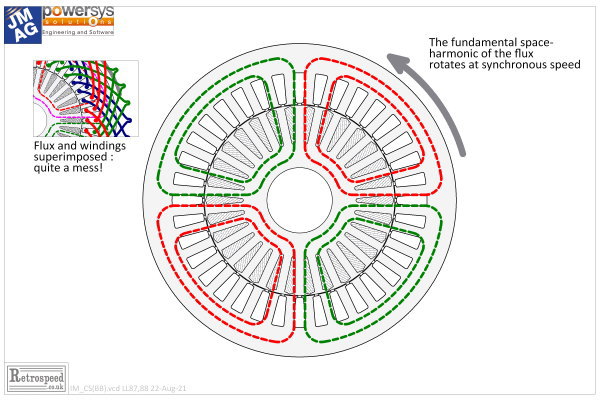
 Fig. 1
In Column 36 we studied the cross-section of an induction motor with 36 slots, 30 rotor bars, and a 4-pole distributed winding. Just by looking at the features of the winding, we were able to determine the number of poles. We made several observations about the design of the winding, and we understood the concepts of synchronous speed and phase sequence. We did all this without any speeches or animated videos; and we used only one diagram without labels, so as to use our imagination to the fullest extent.
Let’s continue! But first allow me to say that I recommend the manufacturers’ videos on the internet. They give a variety of illustrations and points of view, and images of real machines far better than what I can produce here in my workshop. In Engineer’s Diary and the design videos, we are never far away from the fundamental theory; and since the style of presentation has no animation or photographs, we have to use our imagination.
Fig. 1 shows the same motor from Column 36. But the winding has been hidden in the drawing, and instead we have a concept drawing of the flux : the dashed lines in red and green. Imagine the confusion if we superimposed the flux drawing on the winding drawing! The inset in Fig. 1 shows how this would look. And yet we must somehow develop a detailed understanding of both the winding layout and the flux distribution. They work closely together, and this underlines the importance of good diagrams; but it also underlines the importance of a clear imagination. Ultimately, for a complete understanding, we must add the equations, and that is what we do in the videos.
The flux-lines in Fig. 1 aren’t realistic in the fine details. If we wanted completely realistic flux-lines we would simply run a finite-element calculation. The flux-lines in Fig. 1 don’t even meander through the stator and rotor teeth properly: they seem to ignore the magnetic structure. They simply express the idea of a 4-pole field of flux which in each pole crosses the air-gap twice, and returns through the stator and rotor yokes in the tangential direction.
We have to make one more imaginative effort. The flux in Fig. 1 is supposed to represent the fundamental flux. What that means is that if we plot the distribution of flux-density around the air-gap, the fundamental space-harmonic will be sinusoidal and it will have four poles. That is all we’re concerned about. All the details — the passage through the teeth, the spatial harmonics — are literally out of the picture. And yet this notion of the fundamental flux is like a clearing in the forest, because it is the very basis of the operation of the induction motor as well as of many other AC machines.
From the previous Column we understand that the fundamental flux rotates at synchronous speed, and that it is established by a component of the stator current (the so-called magnetizing current). This is an AC current, and it has other components which are added to the magnetizing component by means of the phasor diagram.
Here we are going to focus on what this fundamental flux actually does, and how it interacts with the rotor. The rotor has a set of 30 bars, which are shorted together at both ends of the rotor to make up what is called the “squirrel cage”. Obviously the flux is passing through the cage of bars. But we normally think of it the other way round : when there is a speed difference between the flux and the bars, the bars pass through the flux.
Imagine the rotor rotating at synchronous speed, the same speed as that of the rotating flux. There is no speed difference — no relative motion between the bars and the flux. Nothing happens.
But suppose the rotor slows down a little. Perhaps a load has been applied to the shaft. The bars are rotating slower than the flux, and the relative motion — the bars passing slowly backwards through the flux — gives rise to a generated voltage in them, which causes current to flow. This is basic electromagnetic induction : conductors in motion relative to a magnetic field. Many textbooks, especially old ones, speak of the flux-cutting action, in which the generated voltage in an individual bar is determined by the rate at which the bar cuts through the flux-lines. This historic way of explaining the voltage induced in conductors is actually shaky, because a complete circuit (comprising at least two conductors) is necessary to get a measurable induced voltage. You would certainly not try to use the flux-cutting rule to formulate a finite-element calculation; but following in the tracks of convention we will use it anyway. And so we have voltage, and consequently current, in the rotor bars (provided that there is relative motion between bars and flux).
Now we draw on another precept that occurs everywhere in the textbooks, that the currents in the bars interact with the flux to produce torque. This is true, but the formulation in terms of the force on a current-carrying conductor is, again, not suitable for a serious formulation using the finite-element method. But we will use it anyway.
So, having arrived at this point we have current induced in the bars, and we have torque. We have an induction motor! With all due respect, this is more-or-less where the early developers of the induction motor were, 130 years ago. Like true engineers, they quickly set about maximizing the torque, minimizing the current, optimizing the flux level, and designing and applying this wonderful new invention. We know they were very successful. But in the process, they had to come to some sort of understanding of the relationship between the torque and the speed.
As we’ve said, the rotor has no induced current and produces no torque if it is rotating in synchronism with the rotating flux. The more it slows down, the greater will be the rate of cutting flux-lines (going backwards relative to the flux). The greater will be the generated voltage. But how does the current respond? And the torque?
At this point it is helpful — indeed necessary — to think of the rotor as a simple AC circuit with a source voltage (the generated voltage) which varies in magnitude and frequency with the relative speed between the rotor and the flux, which is called the slip. At low slip, near synchronous speed, the frequency in the rotor is low, and the current is limited by the resistance of the rotor bars and end-rings. As the slip increases, the current tends to increase linearly with the generated voltage and therefore linearly with the slip. We can say that the torque will be proportional to the product of current and flux, and if the flux remains constant in magnitude the torque will be proportional to the current and to the slip. This is the classical operating condition of the induction motor at low slip, near synchronous speed. Indeed, inverter-fed motors operate with a controlled slip which is always low, even though the stator frequency changes over a wide range. This is the main means of controlling the speed — not by varying the slip, but by varying the stator frequency while keeping the slip to a controlled, low value.
When we come to consider line-start induction motors operating from mains-frequency supplies at fixed voltage and fixed frequency, we have to consider the variation of rotor current and torque over a much wider range of slip — from zero slip at synchronous speed to 100% slip when the rotor is at standstill. Over this range, the frequency in the rotor varies from zero at synchronous speed to the supply frequency at zero speed. And in this range, the rotor current is limited not simply by the resistance of the rotor circuits but by the impedance, which is the combination of resistance and reactance.
Reactance is measured in ohms, just like resistance, and it rears its head as a current-limiting effect whenever we try to vary the current too quickly. That’s what happens at high frequency. What’s behind it is the inductance of the circuit, and in fact the reactance in ohms is equal to the inductance in henries times the radian frequency in rad/sec (2πƒ). Since reactance is proportional to frequency, it dominates at high frequency, while the resistance dominates at low frequency. On the rotor, therefore, the current is normally limited by resistance at low slip, but by reactance at high slip.
What this tells us is that as the slip increases, the current doesn’t increase indefinitely, and when the rotor is at standstill the current will be limited by the combination of reactance and resistance.
Now in relation to the torque, a more subtle change takes place with the changing slip and rotor frequency. At low slip, when the current is limited by resistance, it is in phase with the flux. At high slip, when the rotor current is limited by reactance, it is nearly in phase quadrature with the flux: that means, lagging nearly 90̊ behind the flux in time phase. In this condition the torque is again small or zero. It is also zero at synchronous speed, zero slip. Therefore, between synchronous speed and some high-slip condition, the torque must pass through a maximum, and this is called the breakdown torque.
The breakdown torque occurs at a particular value of slip, called the breakdown slip. The breakdown slip is important in determining the overall shape of the speed / torque characteristic of an induction motor. It must occur at a speed below synchronous speed; but in principle it can occur at any lower speed, depending on the reactance and resistance of the rotor circuits. Normally we expect to see the breakdown slip at something like 15−30%, but in some special servo induction motors it is designed to occur close to 100% slip.
The message to take away from this discussion is that the speed / torque characteristic of an induction motor is determined by the resistance and reactance of the rotor circuits (among other things). These impedances depend critically on the shape and size of the rotor bars, and to a lesser extent on the number of rotor bars. The resistance also depends, obviously, on the conductivity of the bars and end-rings. This is not a trivial point because casting imperfections may result in an effective conductivity different from that of the pure ingots that were delivered to the factory.
Is it any surprise, then, that to calculate the design of an induction motor we need the most sophisticated software tools? We have touched on only the basic mode of operation based on the fundamental space-harmonics of the flux and of the stator ampere-conductor distribution. When the parasitic effects of harmonics, core-loss, material properties and other secondary effects have to be included in a design calculation, it is clear that the theory and the software are needed even more. But so is the ability to visualize what is going on. We have attempted here to do that in a limited way for the basic mode of operation.
ご意見ご感想をお聞かせください。皆さま方からの貴重なお声として、今後の参考にさせていただきます。
なお、ご質問に関する回答は致しかねますので、あらかじめご了承ください。


