 Fig. 1
The two previous Engineer’s Diaries were titled A and B: A for vector potential and B for flux-density. This is C, for coils and conductors — and maybe for “crocodile clips” (croc-clips)! [1] Indeed C stands for many things in electrical engineering : current, connectors, circuits, capacitance, . . . but here we will focus on coils and conductors.
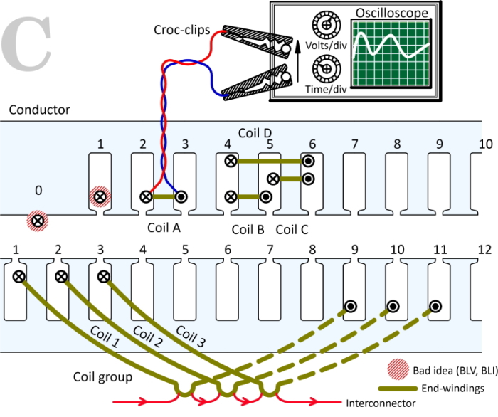
In Fig. 1 we see a conductor 0 on the smooth surface of the stator or rotor of an electric machine. The classical formula for the rotational EMF generated in this conductor is BLV, where B is the flux-density, L is the axial length, and V is the relative velocity between the conductor and the magnetic field. Since about 1880, conductors have been laid in slots, as in slot 1. Yet the BLV formula is still used as the starting-point for the theory of EMF in textbooks, even though B inside the slot is practically zero!
There is a parallel formula BLI for the force on the conductor. Again this is practically zero when the conductor is in the slot; yet this expression is still often used as the starting-point for the theory of torque.
If we tried to use BLV and BLI with a finite-element solution, the results would be horribly wrong.
Let’s try to sort this out. First, let’s be fair to the classical authors and engineers. In early electric machines the conductors were laid on the surface of the stator or rotor, and sometimes in disc coils, so we can see where the BLV and BLI formulas might have originated. They were certainly used in many of the great design engineering textbooks of the early 20th century. For example, Walmsley [1904] says that
We can see here the notion of cutting the lines of flux, the classical explanation of rotational EMF.
In spite of the service which this visualisation has given to generations of engineers, we should nowadays take note of its limitations.
Even when conductors were laid in slots (from the 1880s onwards), engineers continued to use the BLV and BLI formulas — with the same L, the same V and I, but with a different B. Now, B was calculated at the effective surface, or perhaps at the middle of the air-gap, using an equivalent smooth surface which was related to the slotted surface by Carter’s coefficient [1901]. The theoretical justification for using BLV and BLI can be made quite rigorous, given certain assumptions, and the theory of all types of machines was developed vigorously from these foundations to cover every aspect of electrical performance, even though the methods of calculating the magnetic field were crude by modern standards.
That theory of design and performance still holds good today, and is widely used. Although the textbooks often start with BLV and BLI, this mighty and venerable theory does not in fact rely on those formulas in themselves. Indeed when we come to use field calculations using the finite-element method, we find that BLV and BLI are perfectly useless at 0 and 1 in Fig. 1, and we don’t even have Carter’s coefficient to help us, because we are analysing the real machine, slots and all. The notion of flux-cutting is completely foreign to the finite-element method.
The key to this apparent dilemma is Faraday’s law, at least for the BLV formula. Faraday’s law says that the EMF is equal to the rate of change of flux-linkage of a closed circuit. The conductors at 0 and 1 in Fig. 1 are not closed circuits, so Faraday’s law does not apply to them in isolation. The derivation of a practical engineering BLV formula requires the definition of a closed circuit, which means that we have to introduce a return conductor, and that means we will have a complete coil. Some textbooks take the trouble to do that rigorously, while others use the BLV formula and the language of flux-cutting unquestioningly.
Now in Fig. 1 — look! — we have coil A wound in slots 2 and 3. The two conductors, “go” and “return” are already there. The EMF is just as Faraday says — it’s the rate of change of flux-linkage of the closed circuit formed by the coil and its leads all the way to the oscilloscope, and the completion of the circuit through the oscilloscope.
The isolated EMF of the coil itself is a fiction of our imagination, which is made rigorous by minimizing the contribution from any changing flux-linkage in the leads : that’s why the leads are shown as a twisted pair. We can forget about any flux-linkage contribution in the oscilloscope, because its input impedance is just a huge resistance with maybe a tiny bit of capacitance and certainly negligible inductance. Moreover, since the coils in an electric machine generally have many turns, the EMF of the coil is always much greater than any vestigial contribution from the leads, and so we always forget about the leads.
Nowadays the flux-linkage can be calculated directly and accurately for real coils in slots, not relying on Carter’s coefficient or any other gross assumptions such as the shape of the air-gap flux distribution. The EMF is then obtained by differentiation with respect to time, but note that this is the entire EMF which includes the effects of both the rotation and any variation in the currents which are exciting the magnetic field. In electric machines parlance, it includes the rotational EMF and the transformer EMF. To distinguish between these components in a finite-element calculation, we must do two calculations: one in which there is rotation but fixed excitation, and the other with no rotation and varying excitation.
These two finite-element calculations lead naturally to two kinds of elements in the equivalent circuit: the EMF and the inductance. “Inductance” usually means a whole set of self- and mutual inductances, because there are many coils and circuits in a typical machine. It is also possible to incorporate the circuit calculations in the finite-element model, and solve the differential circuit equations together with the field equations; this is effectively what is done in a transient solution (as distinct from a magnetostatic solution). In this case it is not necessary to distinguish between rotational and transformer EMFs, because they are both embedded in the solution.
The separation of rotational and transformer EMF is generally desirable because the equivalent circuit is almost always needed for a wide range of purposes (including the design of the controller). The EMF and the inductance are also central in the design process — not only their basic values but their analysis into harmonic components, leakage components, and so on. There are in fact many different ways in which the finite-element process can be used to calculate and illustrate these properties.
Note that the oscilloscope in Fig. 1 also does not distinguish between rotational EMF and transformer EMF. It measures the total EMF. To isolate one or the other component, we must devise a physical experiment, such as rotating the rotor with fixed excitation. Such experiments are precisely analogous to the processes we must do with the finite-element method, and it may help in formulating finite-element processes to consider the physical equivalent in terms of Fig. 1.
That’s why the croc-clips are used in Fig. 1. They are not intellectually necessary, but maybe they help to remind us of the practical principles. The most fundamental of these practical principles is in fact Faraday’s law (not BLV). There is, by the way, an equivalent treatment for the BLI formula which uses Ampère’s law and energy considerations.
Now there are many electric machines which use coils like coil A, wound around single teeth. The most common example is the small fractional-slot brushless permanent-magnet motor: for example, one with 12 slots, 10 poles, and three phases. This motor can be wound with 6 coils (1 layer, non-overlapping) or 12 coils (2 layers, overlapping), all of them wound around one tooth.
But larger machines tend to have coils spanning several teeth. At the bottom of Fig. 1 we have an example (taken from Video 9) showing one pole-group, that is, a group of three coils associated with one pole of a 3-phase AC lap winding in 36 slots with 2 layers. The coil-span is 8 slots, so coil 1 goes in slot 1 and returns in slot 9, while coil 2 is wound in slots 2 & 10 and coil 3 in slots 3 & 11. These coils are connected in series by interconnectors which are only partially shown in the diagram.
The flux-linkage (and therefore the EMF) of this coil-group can be calculated from the vector potentials at the conductor centre-lines: thus (A1 − A9) + (A2 − A10) + (A3 − A11), multiplied by the stack length and the number of turns per coil. An alternative principle is shown in the upper diagram, where the flux-linkage of coil D is obtained as the sum of the flux-linkages of coils B and C. This is expressed as (A4 − A5) + (A5 − A6) = (A4 − A6). It is possible to build up the flux-linkage of a coil spanning any number of teeth by this method. What we have here is a simple example of the use of “primitive” coils, which are connected by interconnectors to make up the windings of a complete machine. This idea is attributed to Gabriel Kron [1939].
It soon becomes obvious that whatever method we use for compiling the flux-linkage and EMF of a complete winding, the interconnectors are an essential component of the model. That is why classical textbooks use “developed” winding diagrams which show the interconnectors. In Fig. 1 the oscilloscope leads and the croc-clips are, in a sense, illustrating the function of the interconnectors, but only for a single coil.
In the case of simple standard windings the interconnectors can be omitted to give a less cluttered winding diagram, but they must then be “implied” or “implicit” or “understood”. For example, in the lower diagram in Fig. 1, the interconnectors are shown between coils but not between groups of coils. (An example is given in Video 9).
All this is background knowledge, which is essential in the study of windings, especially the layout and configuration of windings in relation to the numbers of coils and the interconnections. This forms a very large area of study which has received much new impetus in recent years, partly because of the development of new windings for automotive traction motors, but also because of the search for improved harmonic performance in connection with induction motors, and the optimization of fractional-slot configurations for all types of synchronous and asynchronous machines (including PM brushless machines and wind turbine-generators). For an example of an authoritative modern contribution to the theory of windings, see, for example, Raziee et al [2017]. Please don’t be alarmed if you see the BLV formula. You can be sure it is used rigorously. But connecting it up with finite-element calculations is what our U.S. friends like to call “a whole new ball-game”.
References :
- Kron G., Tensor Analysis of Networks, John Wiley & Sons Inc., New York, 1939
- Walmsley R. M., Electricity in the Service of Man, Cassell, London, 1904.
- Raziee S.M., Misir O. and Ponick B., Winding Function Approach for Winding Analysis, IEEE Transactions on Magnetics, Vol. 53, No. 10, October 2017.
Note :
[1] Please try an internet search for “Crocodile clips” / Images.


