D is for diameter! — surely the most fundamental of all engineering dimensions, at least in electric machine design. It is so important, we might ask ourselves why computer monitors are rectangular instead of circular! When we look at the cross-section of a machine, everything is bounded by the O.D., the outside diameter (except of course the terminal box). What else is there to see?
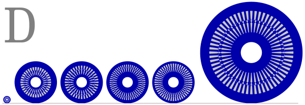
The figure shows a progression of six lamination-sets, starting with a small one of about 42 mm diameter, and ending with a rather large one of 580 mm diameter. The smallest one is around 4 × 10⁷ times larger than the the smallest electric machine ever made, while the largest one is about 10 times smaller than the largest electric machines currently made. So the range of diameters in electric machines is of the order of 6 × 10⁹ to one. Square that number to get the range of cross-sectional areas. Cube it to get the approximate range of volumes or weights.
A company that makes nano-motors would not be expected to have the tooling or the skills to make a 1000 MW hydroelectric turbine generator, although a company that makes simulation software would be expected to serve both of them equally well! The figure shows five IEC motors, four of them 160-frame and one 355-frame.[1] The ‘160’ refers to the shaft height above the deck, so the big one would have its shaft axis 355 mm from the floor, and its diameter is 580 mm or 22⋅835 inches. Shaft height is the commonest measure of motor frame sizes in the world-wide IEC standards (and in the NEMA standards in the USA and other similar standards in other parts of the world). A company that makes IEC-standard motors may be dealing with a range of frame sizes from 56 to 355, which covers a very wide range of power, even within the range of “low voltage” (less than about 1000 V).
These motors have different numbers of poles, the most common being 2,4,6 and 8; and the optimal rotor/stator diameter ratio is different for these cases. In the figure, the 2-pole motor has a diameter ratio of 0⋅55, the 4-pole about 0⋅65, the 6-pole and the 8-pole about 0⋅7. The basic reason for these differing ratios was discussed in Column 19, but we should also note that the numbers of stator and rotor slots are also different. The choice of stator slot number depends on several factors such as the cooling arrangements and the need to have manageable coil dimensions for winding, so the stator slot number tends to increase with size. Not only that, but the choice of rotor slot number is a critical decision that depends on the stator slot number, the number of poles, and the motor duty: that is, whether it is a line-start or inverter-fed motor, whether it is reversible, and so on. Line-start motors are susceptible to harmonic effects during starting, including asynchronous crawling, synchronous locking, and even standstill locking in which the motor refuses to start. Avoiding these is a tricky business for the designer, because there is quite a forest of rules with many pitfalls, and these effects are not easy to calculate. Even more complex is the question of noise and vibration, which is also dependent on the numbers of stator and rotor slots.
At the most basic level of sizing electric machines, it is the rotor diameter that comes to the fore. The reason is that it defines the torque radius for a given force density that can be developed by the product of flux-density and electric loading (amperes per circumferential metre of current-density) at the air-gap. Indeed we often speak of the D2L product as a measure of the size, where D is the rotor diameter and L is the axial length. This goes back to the famous Esson coefficient originally developed for DC motors, but still used today.[3] Another crucial engineering parameter is the L/D ratio of the rotor, which has enormous influence on many electrical and mechanical aspects. Extremely large or small values of this ratio are not practical, and it might be interesting to remember the ‘goodness’ factor attributed to the late Prof. Laithwaite, who argued that the pole-face of an electric machine should ideally be square: in other words 2pL/πD = 1, where p is the number of pole-pairs. Induction motors and salient-pole synchronous machines might be said to follow that notion very roughly (it cannot be described as a rule, not even a rule of thumb). But while other types of machine deviate far from it, their L/D ratios remain mechanically reasonable.
At the other end of the scale, all these machines use wire conductors and there again diameter is the crucial dimension. Typically, wire diameters are in the millimetre range, although a range of roughly 100:1 is found in magnet wire catalogue data. That’s a range of 10,000:1 in cross-section area, which defines the basic current-carrying capacity. Some advanced modern machines use highly stranded conductors (for example, Litz wire), while solid rectangular conductors have become common in hair-pin windings for automotive electrification. As electrical engineers we probably think about resistance in the first instance, but it’s also important to consider flexibility (for winding), and the size of any wire is important in determining its susceptibility to skin effect and proximity effect, (that is, eddy-current effects which greatly increase the losses under high-frequency conditions). What is less often mentioned is the relationship between resistance and weight: the ratio goes with the fourth power of the wire diameter. What that means is that if we are calculating wire weight (important for cost) and wire resistance (important for efficiency), we have to know the wire diameter very accurately if we are to get accurate values for both these parameters at the same time, as we must. Moreover, wire weight is valuable in the estimation of wire length (and from it the mean length of turns), when the resistance is also known. Although these precepts may seem rather humble, they are valuable on the factory floor or in the design office when designs are being validated or when test data is being interpreted.
Another important diameter that stares out at us from the figure is the shaft diameter. The shaft in an electric machine is a sophisticated engineering component. It must be straight. Inevitably it has many changes of diameter along its length, and that means potential sites of fatigue failure which need to be carefully assessed and protected by fillet radii, good balance, and good alignment in good bearings. The lateral stiffness of the shaft is important to counteract the effects of unbalanced magnetic pull, where this can arise, and it also determines the critical speeds (whirling speeds) which may have to be passed through while starting. Especially in high-speed machines and large machines this is an important aspect. Torsional stiffness is also important, not simply to be sure that the shaft can transmit the normal load torque, but also that it can withstand transients which often have oscillatory components and eat up the fatigue life. Diameter, diameter, diameter.
While we have mentioned the ratio of the rotor and stator diameters (outer diameters), we mustn’t forget the difference between the stator inner diameter and the rotor outer diameter. This is not one of the primary dimensions in a stamping catalogue, because the rotor and stator are dimensioned separately, and in engineering drawings the air-gap is almost always found among the tolerances on the main diameters. Yet the air-gap is one of the most critical dimensions to the electrical engineer. Unfortunately the air-gap can become a kind of repository for the errors and tolerances that build up on the mechanical side. Tight tolerance on the air-gap implies extremely tight tolerance on the diameters, which are so much larger. Not only that, but roundness and concentricity are also important, and they complicate matters considerably, not only on the mechanical side but also on the electrical side. Although some rotor diameters (and even stator diameters) are finish-machined, this is not really desirable with laminated components because of the tendency to smear the surface, which increases the surface losses. Diameter, diameter, diameter!
Curiously enough, one of the early methods of analysis of the induction motor was the circle diagram developed in the 1890s separately by Behrend, Blondel, and Heyland.[2] This diagram is a locus diagram of the current phasor in the complex plane, and in those days long before numerical analysis, locus diagrams were popular because they characterized the performance of a machine over its entire operating range, using only a small number of measurements (essentially the no-load test and the locked-rotor test). The circle diagram could be processed on the drawing-board with draughting implements (ruler and compass, basically); Euclidean geometric constructions such as the inversion of circles were commonly used before the slide-rule and certainly before the calculator or computer. But the irony is that the circle diagram from test was far from circular, because of saturation and other effects such as deep-bar effect (eddy-currents). The diameter of the circle diagram might have something to do with the locked-rotor current, but it would never be a neat or obvious measurement. So if we are looking for an aesthetic icon to celebrate the pristine elegance and fundamental importance of diameter in engineering, the circle diagram would be a poor choice!
Note :
[1] These are original ‘academic’ diagrams created solely to illustrate this article; they show typical dimensions but they do not represent any particular product, and they are not supported by any calculation or test data. [2] See, for example, Behrend B.A., The Induction Motor and Other Alternating Current Motors; Their Theory and Principles of Design, Second Edition, McGraw-Hill, New York, 1921; and Thompson S.P., Polyphase Electric Currents and Alternate-Current Motors, E. & F.N. Spon, London, 1895. Both titles are available in the Classic Reprint Series of www.ForgottenBooks.com — recommended reading, with authoritative accounts of early developments. [3] See section 3.3 in Hendershot J.R. and Miller T.J.E., Design of Brushless Permanent Magnet Machines, Motor Design Books, 2010, (The Green Book), www.motordesignbooks.com.
