 Fig. 1 [1]
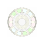
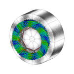
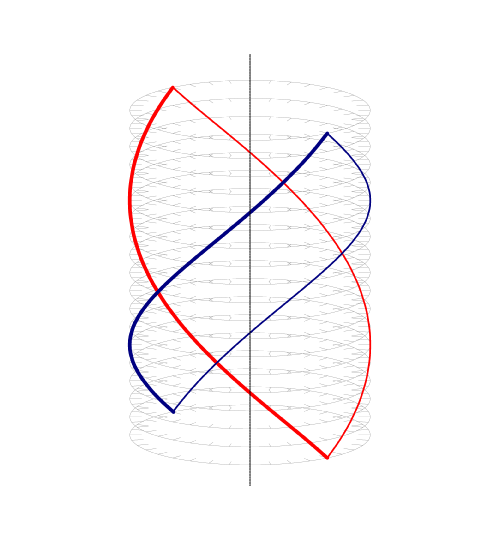
The helical winding (Figs. 1 and 2) was originally examined as a candidate air-gap winding for large 2-pole superconducting alternators at International Research and Development Co. (now part of Rolls-Royce) in the early 1970s; [2]. Subsequently, experimental alternators with helical windings were built in the late 1970s (4 MVA by Hitachi in Japan [5] and 60 kVA at M.I.T. in the USA [6]) , and much work was reported on the design of conductors and their mechanical support and cooling systems. At about the same time the magnetic field of armature reaction was analyzed by Anderson et al [4], with emphasis on the calculation of the synchronous reactance. More recently the analysis was extended by Jumayev et al [8] to include the calculation of eddy-current losses in a permanent-magnet rotor. Very little appears to have been published on the calculation of the EMF, or on physical descriptions or experimental tests on machines with permanent-magnet rotors, although we should be careful to distinguish this bar-wound class of winding from the Faulhaber and rhombic windings used in small DC and brushless DC servo-motors.
This Diary article was stimulated partly by reading about the remarkable development of the hair-pin winding which is now common in highly rated automotive electric traction motors. (An internet search for ‘hair-pin winding’ will immediately produce a great many spectacular examples). These hair-pin windings use conductors that can be loosely characterized as ‘bar-wound’, where two bars forming a U are inserted axially into slots and welded at the remote end. We have seen extraordinary developments in manufacturing and automation to make this possible, and it seems natural to ask whether the helical winding has anything to commend it in similar applications.
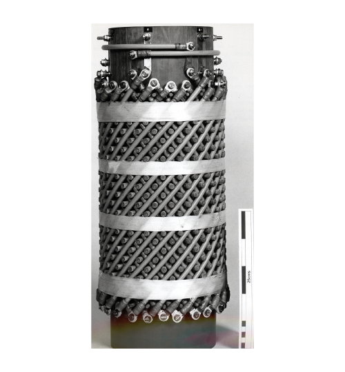 Fig. 2 [3]
Both types of winding require sophisticated 3D finite-element analysis which was simply not available to development engineers at the time of references [2-7]. But let us consider some of the properties of the helical winding in general terms, to see if there might be a case for further study.
Each coil in a helical winding comprises a double helix of conductors ‘going’ in opposite directions, and they can be considered as individual bars with a skew of 180 electrical degrees or one pole-pitch. The classical skew factor in this case is 0.6366, and the overall winding factor will be this value multiplied by the distribution factor which will depend on the phasebelt width and therefore on the number of phases; (six phases would give about 3.5% more than three phases). At first sight we would probably reject the helical winding on the basis of this low winding factor, but against that is the remarkable property that there are no end-windings. Of course connections are necessary, but it would seem that the welding technology developed for hair-pin windings might be applicable.
The absence of end-windings means a reduction in winding resistance, and this reduction is very substantial in a 2-pole winding. The same reduction factor applies to the weight of copper.
In the early work on helical windings, only 2-pole configurations were considered. The saving in copper weight and the reduction of resistance are both greatest for the 2-pole winding, but another important factor is the magnetic field of the rotor. Since the helical winding is inevitably an air-gap winding, the attenuation of the rotor flux-density with radius is very important, and this is significantly less with 2 poles than with higher pole-numbers; [4].
Continuing with the 2-pole machine, consider the fact that most automotive EV traction motors have 8–12 poles and operate at speeds as high as 10,000 rpm; so the fundamental frequencies in these machines are of the order of 800 Hz. If only they were using 2-pole machines the frequency would be 4–6 times lower. The core loss would be substantially reduced and there would be no need for extremely thin laminations. So we should ask ourselves why these machines are using so many poles?
The conventional reason for a higher pole-number is to reduce weight — particularly the weight of the core, but also the weight of the end-windings. A 2-pole helical winding has no end-windings, but since it is an air-gap winding we can expect the magnetic loading to be lower than it would be in a conventional slotted armature, and this reduces the required radial thickness of the core. Moreover, although there are no teeth, the conductors still need mechanical support and cooling, so it is questionable whether the same electric loading can be obtained as in a conventional slotted armature. We can imagine a trade-off in which the core thickness and weight and the flux/pole are lower, while the core length is greater (covering almost the entire length of the winding); the core is also unslotted and built with thicker laminations.
What about the rotor? It is fair to suggest that almost any multi-pole PM rotor could be remagnetized with 2 poles instead of 8,10 or 12 poles, simply by changing the order of polarities of the individual magnets. This would not give an optimal 2-pole configuration but it illustrates the principle. Going one step further, the saliency (that is, the difference between synchronous inductances in the d- and q-axes) might possibly be capable of being increased, if we borrow from the synchronous reluctance motor the well-known characteristic that saliency decreases with increasing pole-number.
Against this possible improvement in saliency, the helical winding will have inherently low synchronous inductances, partly because of the absence of end-windings and partly because of the large effective air-gap. The per-unit synchronous inductance may be lower or higher depending on the balance between the electric and magnetic loadings.
It is not easy to draw a conclusion from these speculative notions. What seems clear is that such a radical change in the armature configuration raises so many basic questions, that a full-scale project would be needed to provide quantitative answers and good conclusions. To my knowledge this class of helical winding has not been taken up for high-performance permanent-magnet motors, although the title of [8] suggests that I may have missed it. That reference is purely analytical and does not mention any particular embodiment or application, so please write and tell me if my searches (mainly in IEEE XPlore) have been in vain!
References
- See Fig. 5.18 on page 24 of the Green Book: J.R. Hendershot and T.J.E. Miller, Design of Brushless Permanent-Magnet Machines, ISBN 978-0-9840687-0-8 Hardback, 2010; ISBN 978-0-9840687-5-32022 on-line, with corrections.
- Ross J.S.H, Anderson A.F. and MacNab R.B., Alternating Current Dynamo-Electric Machine Windings, British Patent No. GB 1395152, 1975
- Miller T.J.E., Transient Magnetic Fields in the Superconducting Alternator, PhD. Thesis, University of Leeds, 1977.
- Anderson A.F., Bumby J.R. and Hassall B.I., Analysis of helical armature windings with particular reference to superconducting a.c. generators, IEE Proc., Vol. 127, Pt. C, No. 3, May 1980, pp. 129-144.
- Watanabe M., Takahashi M., Takahashi N. and Tsukui T., Experimental Study of a Practical Airgap Winding Stator Arrangement for Large Turbine Generators, IEEE Transactions on Power Apparatus and Systems, Vol. PAS-100, No. 4, April 1981, pp. 1901-1910.
- Conley P.L., Kirtley J.L., Hagman W.H. and Ula A.H.M.S., Demonstration of a Helical Armature for a Superconducting Generator, ibid., Vol. PAS-99, No. 4, July/August 1980, pp. 1642-1650.
- Mueller M.A. and Bumby J.R., Magnetic field and inductance of helical armature windings, ICEM 2000, 28-30 August 2000, Espoo, Finland, pp. 627-631.
- Jumayev S., Paulides J.J.H., Boynov K.O., Pyrhönen J. and Lomonova E.A., 3-D Analytical Model of Helical Winding PM Machines Including Rotor Eddy Currents, IEEE Transactions on Magnetics, Vol. 52, No. 5, May 2016, pp. 1-8.

