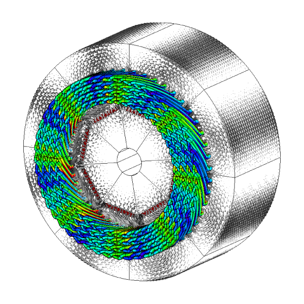
 Fig. 1 Field solution in IPM with hair-pin winding; [1]
(Prof. Chris Gerada, University of Nottingham)
The hair-pin winding has become prominent in drive-train motors for electric and hybrid vehicles, with many creative examples in manufacturing. Although ‘push-through’ hair-pin coils have long been used in other industries, especially in heavy machines, it is probably fair to say that relatively few changes took place before the more recent impact of the automotive industry [2].
In automotive traction the circumstances that favour the hair pin winding seem clear. There is an obvious premium on space and efficiency, while high speed is needed and battery voltage is limited. These factors limit the numbers of turns, while requiring a high slot fill factor. Hair pin windings meet these requirements well. They are often formed as wave windings with straight ‘legs’ pushed through the slots from one end, so that a high slot fill factor can be achieved even with semi closed slots. The two legs are bent in opposite directions and their ends brought into line with the ends of other coils to which they are to be joined, as in Fig. 2. In a complete winding there may be four or more layers or bars in each slot, so that the number of joints will be at least twice the number of slots. The joints are welded in a consistent fashion in the confined space of the end winding with minimal damage to the wire enamel beyond the weld zone, and this process is usually automated. The final assembly is robust, compact, and open for cooling.
Let’s consider some of the features that might affect the making of a 3D finite-element model. At first sight it appears that the coil geometry is more regular than that of random-wound coils. The conductors are solid, which again makes them geometrically simpler than the coil-sides of random-wound coils.
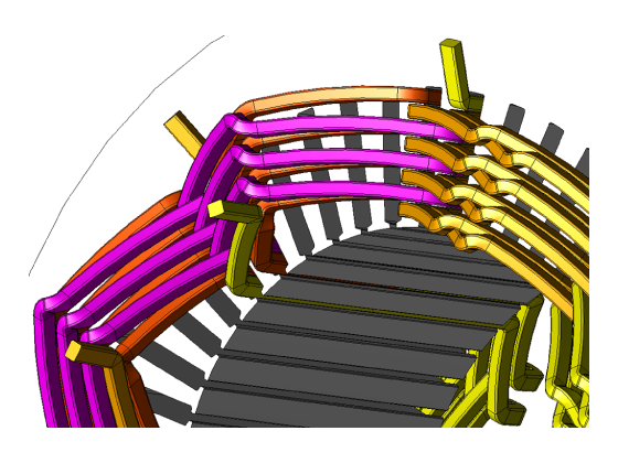 Fig. 2 Geometry of hair-pin windings in JMAG [1]
(Prof. Chris Gerada, University of Nottingham)
The coil-sides of random-wound coils can be modelled approximately as solid conductors when the field is not time-varying (i.e., under DC conditions, or when skin effect and proximity effect can be neglected). But the conductors of hair-pin windings have precise shapes resulting chiefly from the forming process, and the specification of their geometry may be held in the data and programming of CNC tools used in that process. Importing that data into the geometry editor of a finite-element program is clearly a vital step. It would seem that it needs to be done efficiently because it may have to be repeated many times, so that several winding configurations can be analysed.
A complication that arises in the geometry of end-windings and interconnectors is that the winding may have more than one hair-pin geometry, as well as a number of different interconnectors — not only between phase-belts but also between layers. The winding is therefore not a perfectly regular array of conductors and interconnectors, although it will have been designed for near-perfect balance between phases and between parallel paths within one phase. It is shown in all the key references that it is important in manufacturing to limit the numbers of different hair-pin geometries and interconnector geometries, and this limits the number of layers that may be used in practice, even though a larger number would permit the use of smaller conductors with lower AC losses, [1].
The problem of AC loss in the conductors appeared in the earliest days of electric machines. This is not surprising in view of the large conductor cross sections that were used even when the industry was in its infancy. Analysis of the skin effect and proximity effect goes back to the classic work of A.B. Field [3], and of later authors. Such works helped in the design of windings to minimize the AC losses, particularly through the layout of the conductors in the slot and the use of transpositions such as the Roebel bar. For hair-pin windings these problems were addressed in the U.S. Patent by Cai et al [4], which gives a practical account of the choice of the size of conductor bars (to limit the skin effect) and the layout of the coils (to limit the proximity effect). With only one turn per coil there is no scope for transpositions, while the proximity effect in particular is sensitive to the spacing of the conductors in the slot, and Cai points out the advantage of mixing conductors from different phases within the slot. To the extent that this is possible, the objective is to lay out the winding to achieve a configuration which gives the least loss.
This calls for ingenuity in the layout of the coils so as to achieve a well ordered array of leg ends for welding. The layout is also designed to use a coil span that minimizes lower order space-harmonics of MMF. So although the end result may seem at first sight similar to the familiar wave winding of the DC machine, in fact it has many additional features. More recently windings with more than four layers have been developed in the pursuit of even lower AC losses, with smaller conductors and further optimized layout.
The theory of the layout of AC machine windings is held in a set of rules which are largely expressed in integer-logic, closely associated with manufacturing constraints and with Fourier series analysis of the space-harmonic properties. It would not be an exaggeration to say that recent proponents of the hair-pin winding have taken this winding theory to another level. For example Bianchi & Berardi [5] introduce their rules as extensions of the rules that apply to more conventional windings, while the more recent paper [1] by Zou et al from the University of Nottingham gives a comprehensive analysis extending to a larger number of layers. This paper in particular is a fine example of the fusion between classical winding theory, advanced manufacturing, and advanced numerical analysis as illustrated in Fig. 1.
References [1], [4] and [5] are recommended reading for an introduction to this subject, but an internet search for ‘hair-pin winding’ will yield some spectacular physical examples, and even videos of their manufacture. Twenty years ago, or even 120 years ago [6], an engineer could have been forgiven for thinking that the theory of AC machine windings was complete; but the community now working on hair-pin windings has shown us that this is far from true.
Acknowledgement — Thanks to Professor Chris Gerada and his team for providing Figs. 1 and 2. (See [1] below).
References
- Zou T. , Gerada D. , La Rocca A., Moslemin M., Cairns A., Cui M., Bardalai A., Zhang F. and Gerada C., A Comprehensive Design Guideline of Hairpin Windings for High Power Density Electric Vehicle Traction Motors, IEEE Transactions on Transportation Electrification, Vol. 8, No. 3, September 2022, pp. 3578-3593.
- Hendershot J.R. and Miller T.J.E., Design Studies in Electric Machines, Motor Design Books LLC, ISBN 978 0 9840687 4 6, October 2022.
- Field A.B., Eddy Currents in Large Slot Wound Conductors, 22nd Annual Convention of the AIEE, Asheville, N.C., U.S.A., 761 788, June 19 23, 1905.
- Cai W., Fulton D. and Congdon C.L., Multi-set rectangular copper hairpin windings for electric machines, U.S. Patent No. 6,894,417 B2, May 17, 2005.
- Bianchi N. and Berardi G., Analytical Approach to Design Hairpin Windings in High Performance Electric Vehicle Motors, IEEE Energy Conversion Congress and Exposition (ECCE), 2018, pp. 4398–4405.
- Smith S.P., The theory of armature windings, J.I.E.E. (UK), 55, (261), 1916, pp. 18–36.

