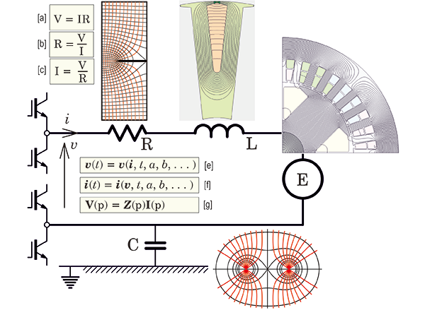
 Fig. 1 An electric circuit
OK — We’ve reached letter ‘O’ in the alphabetic sequence of Diary topics, and Ohm’s law immediately comes to mind. When I was a student, one of my room-mates (a medical student) had to sit a physics test, and he prepared notes, one of which concerned Ohm’s law. To cover every possible variation in the examination questions, he wrote Ohm’s law in all three variants which are reproduced at [a], [b] and [c] in Fig. 1. At the time we considered this to be either crazy or very devious, but that student went on to become a medical doctor of international distinction, and it prompts the serious philosophical question as to whether there is more to Ohm’s law than might at first appear.
Historically, a good starting-point for Ohm’s law is the fact that at first it was not well received, and it was even contested by some leading electricians (as the EE’s of those days styled themselves). Most of the time we associate it with DC circuits, and particularly the property of electrical resistance which is measured in units of [ohm] or [volts per ampere]. We make frequent use of the formula, R = ρL/A, where ρ is the resistivity, L the length, and A the cross-section of a conductor, and we allow for the temperature variation of ρ in using this formula. But many conductors have non-uniform cross-sections, and in some cases it becomes necessary to use numerical analysis to solve for the distribution of current-density and thence the resistance at the terminals. Fig. 1 shows an example of a flat strip conductor with a slit or saw-cut, in which the red lines are streamlines of current and the black lines are equipotentials, and this solution is used to calculate the resistance between the top and bottom edges.
Under pure DC conditions the resistance R is the only impedance element in the circuit in Fig. 1. We call it ‘impedance’ because it impedes the flow of current. Resistance also resists or impedes the flow of current, but impedance is a more general term that includes the effects of inductance and capacitance.
Under AC or time-varying conditions the impedance acquires additional components that are associated with the magnetic fields produced by the current (mainly through the inductance L), and the electrostatic fields produced by the voltage (mainly through the capacitance C). The resistance R now becomes a function of time (or in a pure AC circuit, a function of frequency), owing to the redistribution of current within the conductor caused by varying magnetic fields that pass through it. When these magnetic fields are attributed to the current in R itself, we use the term skin effect; but when they are excited by currents in other parts of the circuit, or in other circuits, we use the term proximity effect. In both cases the internal redistribution of current always increases the apparent resistance. It may also introduce an inductive element into the impedance R, so that under pure AC conditions we might represent that impedance by a complex value R. The inductive component is often ignored, especially in the case of wires and cables that are designed to minimize skin effect and proximity effect; but in flat-strip conductors it may need to be carefully considered.
In electric machines the circuit generally includes another circuit element representing the EMF E generated by rotation (usually of an excited rotor such as a PM rotor or a wound-field rotor). Under pure AC conditions, if the generated EMF has a sinusoidal time-waveform at the operating frequency, the EMF can be treated as a single number representing the RMS (or ‘effective’) value, or more precisely as a complex number E whose magnitude is the RMS value and whose argument represents the phase of the EMF relative to a reference phasor such as the current. In synchronous machines the reference phase is often tied to the physical position (angle) of the rotor.
In general the EMF waveform in electric machines is not a pure sinewave, and in such cases it is very common to use the fundamental harmonic component as the phasor value, so that normal AC calculations can proceed with the complex voltage and current and the complex values of the other impedance elements. But in the most general cases the time-waveform of the EMF needs to be calculated precisely, and the same is true for the time-waveform of the current and the terminal voltage. Harmonics in EMF waveforms arise from the physical shape of the rotor and the distribution of the windings, but they can also be affected by magnetic saturation and the slotting of the stator laminations.
In this discussion it should be clear that we are gradually moving from the simple idea of resistance, through the more general concept of impedance, to the ultimate representation of the circuit in terms of several interacting physical processes. Each of these processes is amenable to numerical analysis — for example, the finite-element method is commonly used to calculate inductance and EMF. In simple cases only the steady-state values are required, and for these it is common to use magnetostatic solutions.
But the more we go into detail, the more complex the model becomes. In time-varying problems the relationship between instantaneous voltage and current at the terminals can be expressed in a general way in the form shown as [e] in Fig. 1, wherein v and i are usually vectors containing a multiplicity of voltages and currents in the several branches of the complete circuit, and not just the single v and i shown in the diagram. (Other relevant parameters a, b, … may appear in these equations). The form [e] can be said to be a generalised statement of Kirchhoff’s first law, which in turn can be characterized as a more general form of Ohm’s law. But even this does not express the action of a simulation tool based on numerical analysis of all the physical processes in the system. For that, equation [f] would be a more definite statement of what such tools actually do. In words, quite simply, we impose voltages at the terminals, and the simulation tool calculates the currents — no matter how complex the behaviour of the various impedance elements.
The equations [e] and [f] are ordinary differential equations in time t, and in electric machines the execution of process [f] implies that the voltage equations [e] must be integrated with respect to time in order to ‘invert’ them with voltage in and current out. Since this is a time-consuming process, it is common to impose the currents as known input variables, to calculate the voltages, and use them to determine values for the impedance elements which then form the so-called equivalent circuit. Once the equivalent circuit is defined, electrical engineers find themselves on familiar territory and they apply the classical methods of AC circuit analysis efficiently (though inevitably approximately, since the equivalent circuit is rarely comprehensive enough to model all possible variations in the behaviour of the system).
One of the major complications in the simulation of electric machines is the fact that they are often fed by power-electronic switching circuits (usually inverters) which introduce switching nonlinearities into the voltage equations of the complete circuit. The switching events take place at high frequency (several kHz), so that if they are to be simulated in a real-time simulation the time-step must be very short, much shorter than most of the time-constants that describe the machine itself. Although this large process is sometimes executed, it is more common to separate the machine model from the inverter model by making what we might call ‘coupling simplifications’ at the terminals. For example, the inverter and the machine might both be represented in steady-state operation by their common terminal voltage and current, expressed as phasors on the machine side and as space-vectors on the inverter side.
Another example of this partition can be found in the DC commutator machine, in which the commutator is itself a switching element — a frequency converter — that converts the AC in the machine armature to DC at the terminals (the brushes). In most cases this process is so smooth and ripple-free that the voltage and current at the machine terminals really do appear as pure DC, even though the physical switching at the brushes and commutator segments is as complex and ‘frenetic’ as anything that goes on in inverters. In fact the conversion from AC to DC in both commutator machines and inverters can be represented mathematically as a mapping or transformation. There are many other transformations in the world of simulation designed to simplify these processes; one of the common ones is Park’s transformation, which maps the AC variables at the stator terminals into DC variables in the steady-state. Park’s transformation is known as a reference-frame transformation and similar notions are used in the theory of space-vectors and field-oriented control.
Another transformation commonly used in transient analysis of circuits is the Laplace transformation (or in machines, the Heaviside transform which is a ‘cognate’ principle). This is expressed in equation [g], with the generalised frequency variable p in deference to Heaviside because of the particularly important contribution he made in connection with electric machine transients. (The symbol s is more often used with the Laplace transform, or jω with the related Fourier transform). These transformations apply to linear systems and so the range of their applications in machine problems is quite limited.
The capacitive element in Fig. 1 is included for completeness, although it is relatively uncommon in machine calculations. It is, however, important in the analysis of electrostatic stress on insulation, and in the analysis of the propagation of high-frequency signals or wavefronts through the machine. The physical phenomena of first-turn failure and electro-discharge effects in bearings are two of the most important practical cases, and while neither of these has any bearing on the normal operation of the machine, both of them can cause serious damage and premature failure.
Many years ago I happened to be walking along a perfectly ordinary boulevard in Nürnberg in Germany, and as I passed a small public garden my eye fell on a small plaque placed in the grassy verge a few feet back from the footpath. It was a commemoration of the birthplace of Georg Simon Ohm. That city has a long and illustrious heritage in electrical engineering, and I must say it was a memorable event, however small and incidental, to pass by that memorial plaque on a busy morning. When Ohm gave us a logical relation between the voltage and current in an electrical circuit, how could he possibly have imagined the complexities we handle daily today?
Further reading
J.R. Hendershot and T.J.E. Miller, Design Studies in Electric Machines, 2022 (the ‘Blue Book); sales@motordesignbooks.com
Y.H. Ku, Electric Energy Conversion, Ronald Press, N.Y., 1959.


