 Fig. 1
Axial-flux machines are currently in vogue. With an internet search we can quickly find numerous examples, including many videos of home-made machines and some notable products and prototypes with very high power/weight ratios. Virtually all the current machines are nonsalient-pole machines using high-energy permanent-magnets, and various pole-numbers are used. The stator windings could in many cases be used with a wound rotor instead of a permanent-magnet rotor; and we can find many examples from the late 19th century, such as the Ferranti-Thomson alternator of 1882 and an ‘Alternate-current machine’ made by Siemens-Halske. Many of the AC machines of that era were used for lighting. They often had stationary field windings and rotating armature windings with slip-rings, and they were built with various numbers of phases including 1,2, 3 and 4, [1].
In this Engineer’s Diary the idea is to explore the electromagnetic configuration of one of these historic machines to see what we can learn about two particular aspects: (1) the mechanical design and method of manufacture, and (2) the method of calculation for the generated EMF and the inductance. It may be that the exercise is relevant to the design of modern-day machines and/or to our current thinking about methods of analysis.
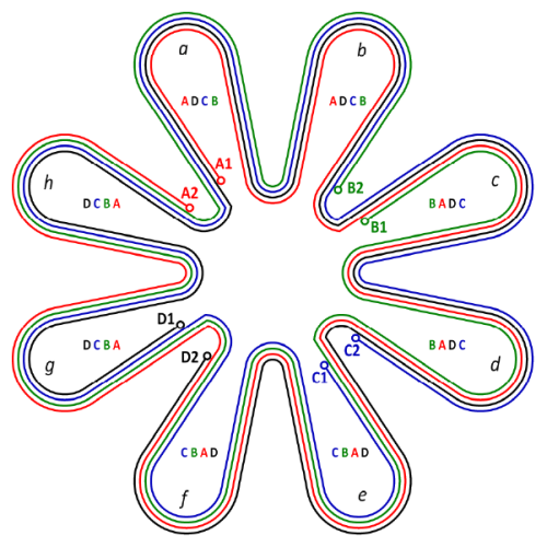
Fig. 1 is reproduced from Walmsley’s Fig. 526 [1] of the Ferranti-Thomson armature winding, in which one phase comprises four bands or strips of copper laid up in layers. The starts and finishes of each band are labelled A1−A2, B2−B2, C1−C2, and D1−D2. Walmsley’s term ‘band’ is descriptive of the physical or mechanical elements of the winding, and he gives the dimensions of each band as 1.25 × 0.07 inches, or about 32 × 1.8. Modern electrical engineers might prefer to think of each band as a ‘section’ of winding, and we will see that Fig. 1 shows a single phase with four sections.
The reconstruction in Fig. 1 uses colours red, green, blue and black to distinguish the four sections more clearly. Starting at terminal A1, we can trace the red section through a series of eight loops a, b, c, . . . h noting that the individual loops are all open, until we reach the return terminal A2 after traversing the entire 360°. In loops a and b the red section is on the innermost layer, but the green section joins at B1 and it occupies the innermost layer through loops c and d, displacing the red section outwards to the next layer. Likewise the blue section joins at C1 displacing the red and green sections outwards by one layer, and finally the black section joins at D1 displacing the red, green and blue sections outwards by another layer. The black section occupies the innermost layer through loops g and h.
In the final assembly each section occupies each layer for two loops in succession, thus occupying all four layers in turn, as indicated by the labels ADCB, ADCB, BADC, BADC, CBAD, CBAD, DCBA, DCBA marked in the respective loops a, b, . . . h. All four sections are identical in shape. However, the sections are not perfectly regular in shape, because of the displacements necessary to accommodate the neighbouring sections in such a way as to achieve symmetry among the four sections. We can see several features of this ‘irregularity’ : differences in the sizes of the inner loop ends, deviations in the angular positions of the conductors resulting in irregular ‘coil-pitch’ or ‘span’, and a ‘kink’ in the conformation of each section where it changes layer. (This kink has been left unfaired by any fillet radius in Fig. 1, so that it can be seen more clearly). The conductors are not quite radial, which means in effect that they are slightly ‘skewed’, but the skew is not uniform or regular in the sense that we normally expect in windings.
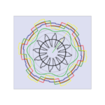
The complete machine will have two sets — that is, two phases — of four sections each (that is, twice what we see in Fig. 1, with one set displaced by 22.5° from the other). It is shown with one section of one phase in Fig. 2 with a 16-pole permanent-magnet rotor. If all four sections of one phase were connected in series each phase would have 4 × 8 = 32 turns in series per phase. Not 4 × 16, because each section links only half the magnet poles: this is a ‘consequent-pole’ arrangement.
The electromagnetic calculations required with such a machine are the same as those required in any machine — that is, the resistance, inductance, and EMF. The resistance is easily calculated from the cross-section of the bands or sections and their overall length, but the inductance and EMF require a 3D field calculation (as is the case with all axial-flux machines).
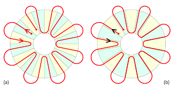 Fig. 2
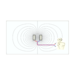
Fig. 2 shows just one section, the red one A1−A2 with the rotor in two positions (a) and (b). The red arrow-heads in Fig. 2(a) show the directions of EMF in two successive conductors which are passing magnets of opposite polarity. The arrow-heads are related to the v × B formula for the EMF in a conductor moving with velocity v relative to a magnetic field of flux-density B, and this is perfectly adequate for checking that the conductors are arranged and connected correctly. However, that formula is not practical for calculating the EMF because it requires the component of B normal to the conductor at every point along the entire length of the section, and the velocity vector at every point (which is by no means uniform all along the length of the section). The formula in its ‘BLV’ form was probably used by the 19th century pioneers, who may have had no other way to estimate the EMF, and certainly lacked any 3D numerical field analysis.
A better way is to calculate the line-integral of the vector potential along the entire length of the conductors, giving the flux-linkage of each section at its terminals. This is indicated by the black arrows in Fig. 2(b) with the rotor in such a position as to maximize the flux-linkage of the red section. Again note that the red section links only half the magnet poles. If the line-integral is repeated over a range of rotor positions at intervals Δθ, the EMF can be estimated by the difference formula ωmΔψ/Δθ where Δψ is the incremental change in flux-linkage from one step to the next, and ωm is the angular velocity. In constructing the necessary line integral, the vector potential can be averaged over the cross-section of the band to take into account any variation of the field across its cross-section (in both the radial and axial directions). Of course this requires a lot of number-crunching, but that is unavoidable with axial-flux machines if accurate design calculations are required.
The same line-integral of vector potential can be evaluated again with current in the winding, and the magnetization of the magnets set to zero. The flux-linkage will then give the inductance — the self- inductance if the current is in the same phase, and the mutual inductance between phases if the current is in another phase. It may well be with most axial-flux machines that the inductance does not vary with rotor position, in which case this calculation will require much less number-crunching than the EMF calculation.
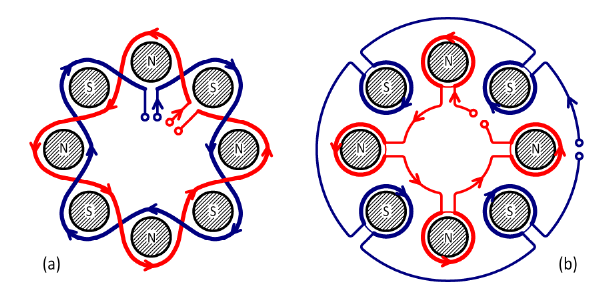 Fig. 3
Walmsley’s description of the Ferranti-Thomson alternator includes a diagram of the ‘electro-magnet’, that is, the field system; Fig. 3(a) is a coloured rendition of this diagram. It shows only eight poles (not 16 as in Figs. 1 and 2). We might expect the field-pole cores to be wound with individual coils, as in Fig. 3(b); but Ferranti has two sinuous loops, one of which links all the N pole cores while the other links all the S pole cores. Each of these loops can be wound with multiple turns, and again each one of them is in a ‘consequent-pole’ configuration. The loops can be connected in series or in parallel, and of course the current is DC.
The inductance of this circuit can be calculated using the finite-element method in the same way as for the armature winding discussed earlier. The calculation can be extended to the mutual inductance between the electro-magnet winding and each phase of the armature winding, by calculating the flux-linkage of one with current flowing in the other.
The historical record abounds with the ingenuity of the early machine designers, and it is possible to see a trend beginning with Gramme windings followed by a variety of axial-flux and some homopolar machines, quickly overtaken by the drum-armature machine and the familiar cylindrical-rotor radial-flux machines that are so common today. Axial-flux machines and concepts have never disappeared but the recent revival of interest in them seems to be driven by two factors that are relevant in different sectors. One is the ease with which ‘home workshop’ models can be fabricated. The other is the possibility of high power/weight ratios which, however, are not inherent in the configuration but require advanced magnetic materials and sophisticated methods of cooling and construction. These personal observations are rather cursory and not based on exhaustive scientific study, but it clearly is the case that the march of invention is far from over.
Further reading
[1] R. Mullineux Walmsley, Electricity in the Service of Man, Cassell & Company, London, 1904, pp. 537-540. [2] J.R. Hendershot & T.J.E. Miller, Design Studies in Electric Machines, Motor Design Books LLC, 2022, sales@motordesignbooks.com ISBN 978-0-9840687-4-6
