 Fig. 1
The famous Park’s equations for the d- & q-axis voltages in synchronous machines were developed from the concept of sine-distributed armature ampere-conductors, [1]. The fundamental or ‘working’ harmonic was isolated from a complex pattern of space-harmonics by Fourier series. Almost the entire classical literature on AC machines and windings relies on the same analysis by Fourier series, and yet it is rare to find any graphical illustrations of the harmonic waves in question, [2]. What we find instead is the raw mathematics, often daunting in its complexity even in the earliest works. Only a few simple static diagrams can be found, even in the most erudite papers and the most didactic textbooks. For the poor struggling student of AC machines or windings, it’s a matter of unrelenting, hard-to-digest mathematics every step of the way.
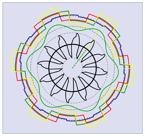
Some of these spatial distributions are drawn in Fig. 1 which is a ‘still’ from the animations in Videos 46-48. In those videos some of the waves pulsate while others rotate, and in the case of the stator ampere-conductor distribution (the yellow wave in Fig. 1) it changes shape as it rotates. The engineers of Park’s generation (and of Blondel’s generation 30 years earlier) did not have the means to produce animated displays of these waves, but they certainly had clear, vivid imagination coupled with skill in the application of Fourier series (not the FFT) and the associated Euler formulas for the coefficients. With these analytical tools they produced the dq-axis models which have served the industry for a century, and which have flourished even more spectacularly since the introduction of current-regulated PWM inverters, field-oriented control, and modern synchronous machines like the brushless PM AC motor.
Park & Co. certainly could have drawn a diagram like Fig. 1 had they been so inclined. They would have had to use geometrical drawing instruments — mainly compass, ruler, and pencil on their large drawing-boards, possibly with french curves and home-made templates constructed using the theory of locus diagrams. But no matter how well they could have reproduced a static image like Fig. 1, to make it rotate they would have had to make hundreds of variants and ‘shoot’ them with a movie camera borrowed from Hollywood (or perhaps Edison already had one in his vast store of inventions at GE).
In contemplating Fig. 1 (I will try to describe it in just a minute), one begins to wonder whether we would ever have acquired the dq-axis transformation or Park’s famous voltage equations in dq-axes, if we had started with the animated displays in Videos 46-48. Fascinating, mesmerizing, entertaining, colourful and ‘cute’ as they may be, they do not easily explain the essence of the AC machine; and they certainly do not produce the equations needed to calculate it. They can embellish the classical theory with colour and movement, and they can give striking illustrations of certain aspects; but the hard fact is that without the rigorous mathematics of Fourier’s series we would be in the dark. Even with time-stepping total simulation of a rotating machine, with instantaneous values of flux-linkage and torque and everything else, we might have fantastic accuracy and insight, but the harmonic essence of the AC machine would not be apparent.1
Let’s describe the harmonic wave diagram in Fig. 1, to see a little more clearly what all this means.
The black circle in the middle represents the net instantaneous torque obtained by integrating the air-gap shear stress (the tangential Maxwell stress) over 360°. It is drawn as a circle with radius proportional to the integral of the product of two harmonic series (Fourier series), one representing the wave of stator ampere-conductors (yellow) and the other representing the wave of ‘rotor flux’ (green). By the principle of ‘orthogonality’, only harmonics of like order make non-zero contributions to this integral, and this is represented by the radius of the black circle. As time progresses, the yellow stator wave and the green rotor wave both rotate. The yellow stator wave continually and cyclically changes shape because its spatial harmonics rotate at different speeds, but its working (or ‘fundamental electrical’) harmonic rotates at synchronous speed — synchronous, that is, with the green rotor wave which is rotated mechanically with the rotor.2
When the torque is constant, the radius of the black circle remains constant as the waves rotate. If there is torque ripple, this radius grows and shrinks periodically at the torque-ripple frequency. There are two main ways in which this can happen, bearing in mind that net torque is always the result of interaction between space-harmonics of like (equal) order, and never the result of interaction between space-harmonics of unlike (unequal) order.
The first is pole-slipping, which occurs when the working harmonic of the stator ampere-conductor distribution (the yellow wave) is rotating at a speed different from that of the rotor and its green flux wave. The pole-slipping torque alternates at the slip frequency (which in a synchronous machine is the pole-slipping frequency); and while its average over time is zero, the peak values can be extremely high.
The second is produced when the fundamental stator and rotor waves are rotating in synchronism (not pole-slipping), but one or more spatial harmonics of the stator wave rotates at a different (asynchronous) speed. For example, the 5th spatial harmonic of the stator wave rotates backwards at 1/5th the synchronous speed. If for example we have a 12-pole machine fed with sinusoidal AC at 50 Hz, the synchronous speed (and in this case the rotor speed) is 50/60 × 12/2 = 500 rev/min, so the 5th harmonic wave rotates backwards at 100 rev/min. We can say that its synchronous speed (that is, the synchronous speed of the 5th harmonic) is −100 rev/min. Relative to the rotor, the speed of the 5th harmonic wave is −100 − 500 = −600 rev/min, and if this is normalized to the 5th harmonic synchronous speed of the harmonic wave we get −600/(−100) = +6. This is defined as the slip (of the rotor, relative to the harmonic wave). By the principle of orthogonality, the 12 fundamental rotor poles produce zero net torque interacting with the thirty 5th-harmonic poles of the stator wave. So where does the torque ripple come from? It can come only from a 5th harmonic of the rotor wave, and it will have a ripple frequency six times the fundamental line frequency. In a similar way, the 7th spatial harmonic of the stator wave interacts with a 7th spatial harmonic of the rotor wave to produce another 6th-harmonic component of torque ripple. The 11th and 13th spatial harmonics of the stator wave interact with like harmonics of the rotor to produce 12th-harmonic components in the torque ripple. A nonsalient-pole rotor whose flux is distributed sinusoidally at the working space-harmonic will have no torque ripple arising from spatial harmonics in the stator ampere-conductor distribution.
The torque ripple that arises from spatial harmonics is generally much smaller than the pole-slipping torque ripple discussed in the previous paragraph, because the space-harmonics of both the stator and the rotor are generally smaller than the fundamental or working harmonic component. There may, however, be several different harmonic components with different frequencies. Provided that the time-waveforms of the stator currents are sinusoidal and balanced, they will all have zero average over time; but they can still be troublesome in exciting torsional resonances, and they may be associated with vibration and noise.
Both types of torque ripple are completely separate from the phenomenon of cogging torque in brushless PM motors. Unlike cogging torque, they are zero when the current is zero. This means that they cannot be felt by turning the rotor by hand when the motor is sitting free on the bench. The torque ripple can exceed the cogging torque when the motor is running, and it may easily be overlooked especially when the motor has low cogging torque (giving the impression of inherently smooth torque).
Two other features of the animated display in Videos 46-48 may be worth mentioning. One is the demonstration of the production of a rotating resultant ampere-conductor distribution from the three static pulsating or alternating distributions of the individual phases, whose axes are displaced by one-third of a double-pole-pitch and whose currents are phase-shifted by 120° relative to each other in time. Every electric machine textbook gives an account of the production of a ‘rotating field’, sometimes with simple static drawings of sinewaves, but never so vivid as the animated display including harmonics.
The other feature is the black ‘floret’ in the middle. This is a polar plot of the air-gap shear stress around the air-gap. It is very wavy as it comes from the product of the stator and rotor waves, but its integral around the air-gap is constant when the stator and rotor waves contain harmonics of the same harmonic order rotating synchronously. The floret is what we would calculate using the Maxwell stress tensor, at each rotor position; to get the time-average torque from that, we would have to rotate the rotor and repeat the calculation a great many times. As we will discuss in Diary No. 68, it is often better (and quicker) to estimate the average torque using the dq-axis torque equation, with flux-linkages computed by the finite-element method. This can often be done at a fixed rotor position; see examples in [3 & 4].
In the next Diary we will review some more practical aspects of the harmonic effects, and take a look at the extraordinary simplicity of the average-torque equation in dq axes. Please enjoy the videos, and any comments will be very welcome.
1 The FFT does not distil this ‘harmonic essence’, because it produces only data (often with spurious noise) with no mathematical expression of the underlying electromagnetic ‘mechanisms’, and no formulas for the harmonic coefficients. Moreover, the FFT does not recognize the phase sequence of harmonics and it is poorly adapted to deal with imbalance and symmetrical components.
2 The spatial harmonics of the green rotor wave all rotate at synchronous speed, if permeance variations due to stator slotting are neglected. These permeance variations give rise to cogging torque and EMF ripple, neither of which is included in the animated wave model.
Further reading
[1] R.H. Park, Two-Reaction Theory of Synchronous Machines, Transactions A.I.E.E., pp. 718-727, 1929.
[2] R. E. Doherty and C. A. Nickle, Synchronous machines I – An Extension of Blondel’s Two Reaction Theory, Transactions A.I.E.E., pp. 912-947, 1926. See Fig. 1.
[3] J.R. Hendershot & T.J.E. Miller, Design Studies in Electric Machines, Motor Design Books LLC, 2022, sales@motordesignbooks.com ISBN 978-0-9840687-4-6
[4] Nicola Bianchi, Electrical Machine Analysis Using Finite Elements, Taylor & Francis, 2005, ISBN 0-8493-3399-7

