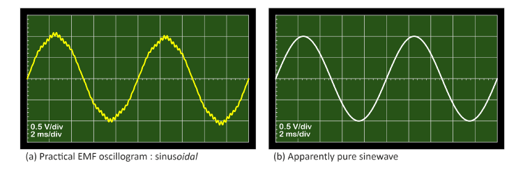
Fig. 1 Sinusoidal and sine
In a practical rotating electric machine it is not possible to generate a perfect sinewave EMF waveform of the form sin ωt. We are, however, concerned with sinusoidal waveforms, in which the suffix ‘-al’ or ‘-oidal’ means ‘like a sinewave, but not necessarily the same as a pure sinewave’. The term ‘sinewave’ does not need the adjective ‘perfect’ because it is by definition a pure mathematical form with no imperfection (no harmonics). But the term ‘sinusoidal’ covers waveforms of different quality — sinusoids — all of them like a sinewave, more or less. Usually, the closer to a sinewave the better.
In testing electric machines it is common to see waveforms (oscillograms) like the one in Fig. 1(a), which has noticeable harmonics including tooth-ripple harmonics.1 In many cases this waveform would be acceptable; but for very smooth, efficient, low-noise operation with high controllability it would not be acceptable and it would need to be improved by one or more of the design changes discussed below.
The sinewaves in Fig. 1 may look good on the oscilloscope, but even the experienced eye is not reliable in discerning very low levels of harmonics, so the quality of these waveforms cannot be precisely defined without much more sophisticated tools than an inexpensive oscilloscope display.2 Strictly speaking a pure sinewave cannot be represented at all on a screen with finite resolution and relatively imprecise pixel shapes, to say nothing of the imperfections in the lens of the human eye. It could even be argued that a pure sinewave cannot be represented exactly on a digital computer, although the errors can in principle be made ‘as small as we please’.
Turning to the engineering practicalities, three questions arise. (1) How close to a sinewave can we get? (2) By what yardstick should we measure the quality of a given waveform? And (3) what principles should we follow in designing a machine to produce a good sinusoidal EMF waveform?
Question (1) does not have a definite simple answer. I would answer it by saying “it depends how you want to measure it”, or “it depends how much money you want to spend”, throwing the uncertainty back into the lap of the questioner. It’s a soundbite question, and engineers don’t place any value on soundbite answers (except in jest).
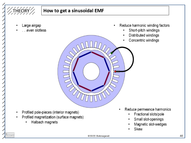
Fig. 2 Sinusoidal EMF in an engineering seminar
Question (2) is a serious engineering question with a formal scientific and mathematical basis. The common rigorous answer is that we analyse the waveform into harmonic components by means of Fourier series (not the FFT), and we then form a ‘goodness factor’ or ‘figure of merit’ using some combination of the harmonic amplitudes (coefficients). Common examples are the crest factor (peak-to-RMS), the form factor (RMS to rectified mean), and the total harmonic distortion (THD). These all have precise definitions and are easily computed from the harmonic coefficients. But there are many others. In some cases we might pick one harmonic — often the third — and characterize the quality of the waveform simply by quoting the percentage of third-harmonic. This would be appropriate in cases where the third–harmonic is known to be more troublesome than the ‘non-triplen’ harmonics (those of orders 6k±1, k = 0,1,2. . .), and there are several examples of this in 3-phase electrical systems. Traditionally it has been common to tolerate a certain level of third-harmonic in the ‘phase’ EMF waveform (line-to-star-point in a star-connection), while concentrating on reducing the 5th and 7th and other non-triplen harmonics — with the justification that the triplen (triple-n) harmonic EMFs cannot produce any triple-n current in a 3-wire connection with no neutral conductor, because of the zero phase sequence of these harmonics. In such cases the line-to-line EMF waveform may look closer to a sinewave than the line-to-star-point waveform, because it does not contain any triple-n harmonics. For machine designers working with these practices, the definition of waveform quality is somewhat specialised to their conventions, although THD and other factors (such as telephone-interference factors) will usually be important as well.
Question (3) is the crunch question for the machine designer, and the starting-point must be Faraday’s law, 3
In plain words, the voltage induced in a winding is equal to the time rate of change of its flux-linkage ψ. If the angular velocity ω = dθ/ dt is constant (as would normally be assumed in any basic calculation or measurement of the EMF), this implies that we need a sinewave variation of flux-linkage ψ with rotor position θ.
In simple terms we need one or both of two elements to achieve this ideal. One is a peripherally sine-distributed flux wave produced by the rotor, which we can call ‘sinewave flux’ for short. Not sinusoidal flux, because (according to the nit-picking definitions in the first paragraph) that would allow space-harmonic components to creep in, as long as the flux distribution looked reasonably close to a sinewave. Here we are looking for a perfect sinewave, nothing less.
The second requisite element is a winding that links the flux, or as much of it as possible, to produce a temporal sinewave of flux-linkage at its terminals. The ideal conception of this winding is one that is capable of linking the sinewave flux, but incapable of linking any space-harmonic components of flux; this we can call a ‘sine-distributed winding’.
The question arises, as to whether we need both these elements together. In theory we need only one of them. By definition, a sine-distributed winding links only one space-harmonic of flux, so it does not matter if the rotor produces space-harmonic components of flux other than the fundamental working harmonic having the same number of poles as the winding. On the other hand, if the rotor produces a perfectly sine-distributed flux-wave, the rate of change of flux-linkage with rotor position (and therefore the EMF) will be a perfect sinewave regardless of the winding layout.
In practice neither of these two ideals — neither the sine-distributed flux nor the sine-distributed winding — is attainable. Therefore the machine designer must strive to minimize the unwanted harmonic content in the combined effects. As to whether more emphasis should be placed on the rotor as a source of sinusoidal flux, or the winding as a producer of sinusoidal flux-linkage, that is a matter of engineering compromise in every individual case, with a large number of variables. Welcome to the world of the electric machine designer.
Fig. 2 is a well-used graphic from a seminar given often in Europe, which attempts to summarize some of the well-worn methods. Starting at the top left, one of the useful tricks is to increase the air-gap length. It is well known that cogging effects (also characterized in terms of ‘permeance harmonics’) are attenuated fairly quickly as the air-gap increases, and this is important because ‘tooth ripple’ is one of the most annoying and bothersome features of imperfect EMF waveforms. As a completely separate matter, higher-order space-harmonic components of rotor flux are attenuated across the air-gap faster than the working harmonic (the fundamental), although it may require an inordinately large air-gap to get the full benefit of this effect. The ultimate strategy is to use a slotless stator, that is, an ‘air-gap winding’, and although this is sometimes done there is a price to pay in torque density and Joule losses in the stator conductors exposed to the rotating flux.
Because of the limitations of these methods, we also see the use of profiled rotor pole surfaces (‘tapered air-gaps’), which have been used in wound-field salient-pole synchronous machines for at least a century, [3,4]. This method is now common in IPM machines; (see [1], p. 32). In surface permanent-magnet rotors, the Halbach magnet array is acknowledged to produce a flux-distribution that is not only low in space-harmonics, but may also be very strong (high peak air-gap flux-density), [2].
Turning to the winding distribution, the classical methods used in AC machine windings are well known and well documented: namely, short-pitching, spread or distribution; and skew, [2]. (Skew may be applied to the rotor or the stator). In single-phase induction motors, concentric windings with as many as six coils per pole may be used with different numbers of turns, to produce a winding with very low harmonic winding factors and especially to attenuate the third harmonic. In fractional-slot machines with single-tooth coils the flexibility of the distributed winding may be lost, but compensated by the use of fractional-slot windings having two or more ‘repeatable units’ with a relative phase-shift that helps to eliminate some of the unwanted harmonics (although these windings may introduce harmonics of unusual orders including sub-harmonics having pole-numbers less than the working harmonic). In the deep and extensive archives of winding theory we can find extraordinary studies of winding harmonics that would match Copernicus’ or Kepler’s analysis of the motion of the planets: for example [5-8], with more references in [2]. This work is still developing today under the impetus of the hair-pin winding and multi-phase machines [9]; (see Engineer’s Diary No. 49).
At the bottom right of Fig. 2 is a list of some of the methods used to reduce the permeance harmonics (in effect, to get rid of cogging effects and tooth ripple). These methods often improve the attenuation of the main space-harmonics of the rotor flux.
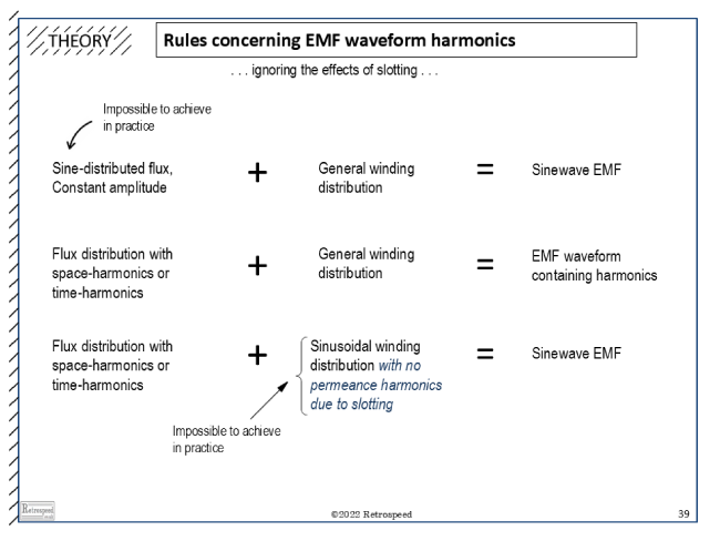
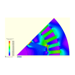
Fig. 3 Principles of EMF waveform harmonics
Finally Fig. 3 summarizes some of the theoretical principles used in this discussion.
How close to a sinewave can we get? I think many engineers would be surprised to see the visible level of harmonics in the EMF waveform of many motors that work perfectly well, that are not particularly noisy, and do not appear to produce excessive torque ripple. Many perfectly adequate AC motors have EMF harmonics that are clearly evident in an oscilloscope trace. But equally, I think many engineers would be surprised to see how little distortion there is in some of the finest, smoothest, quietest, and most efficient servo motors and even large motors for challenging applications where noise, torque ripple, and high control performance are required. So the answer seems to be that we can get pretty close when we have to. And did numerical finite-element analysis contribute in any of these cases? Probably in all of them.
Notes
1 The harmonics in Fig. 1(a) are 2% 3rd , 2% 5th, −2% 7th, 2% 35th, and –2% 37th, with the fundamental at 100% and 5% of a subharmonic at half the fundamental frequency.
2 An irritating feature of some oscilloscopes is the horizontal division of the graticule into 10 divisions. 12 would be better for displaying periodic waveforms, for then we could see 30°, 60°, 90° etc. quite naturally. Decimalisation at all costs is not always the best idea. As to why the circle is so elegantly divided into 360°, we must probably go back to the ancient Babylonians.
3 The ‘sink’ convention is used for the sign of the induced voltage, which makes the negative sign in this familiar equation unnecessary. Lenz’ law is not challenged by this convention, and remains valid as the rule that determines the polarity or direction of the induced voltage. Note that while flux is a distributed field quantity, flux-linkage is a terminal quantity or circuit quantity (the time-integral of the inductive voltage).