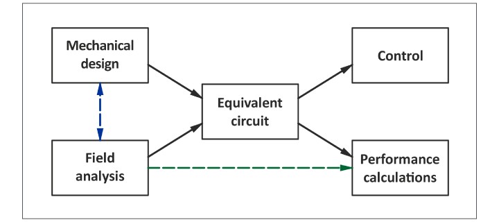
Fig. 1 Areas of electric machine theory and calculation
We are sometimes told that there are two theories of electric machines: the field theory and the circuit theory. If we look through almost any traditional textbook on electric machine theory and design, we will see circuit diagrams and equations for calculating equivalent-circuit parameters and performance characteristics; but very little evidence of serious field analysis (particularly using numerical methods). Conversely if we look through many textbooks on finite-element analysis we will see plenty of sophisticated solutions to Maxwell’s equations; but very little of the classical theory of design and performance. It is only in recent years that we have seen attempts to publish a comprehensive treatment of both divisions of the subject in the same volume. (But see [1] and [3]). There is even a third division, control engineering, which is a substantial subject in its own right; and textbooks in this division tend to have very little treatment of either the field theory or the circuit theory of electric machines. These observations merely reflect the specialization that we see in modern technology. The various divisions of a subject apparently so focussed as electric machines are so vast that a single author could hardly be expected to encompass them all. Similar cases have been treated in the past in books with multiple authors, but it is difficult to produce a unified treatment; (see [4] and [5]).
But it pays to consider what links these specialized areas together. One answer to that is the equivalent circuit. (Figs. 1-3).
The equivalent circuit ‘speaks’ to all three major divisions of electric machine theory — field theory, circuit theory, and control. It also speaks to a fourth division, arguably the most important division: the mechanical and physical design of the machine. The importance of this does not need any elaboration, but a mechanical engineer engaged in the design of, say, an induction motor cannot afford to ignore equivalent-circuit parameters such as leakage inductance or rotor resistance. This merely highlights the fact that the equivalent-circuit parameters are determined by the physical design, and in order to calculate them the starting-point will be the engineering drawings that define the shapes, dimensions, and materials. This is true regardless of the method of calculation, whether it be the finite-element method or a more traditional method.
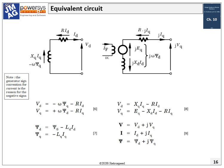
Fig. 2 Equivalent circuit of synchronous machine in dq axes 1
Once the equivalent circuit is defined (together with all its parameter values), performance and control calculations can proceed independently of the mechanical design and the field analysis.
The equivalent circuit can therefore be described as ‘decoupling’ the separate areas of theory and calculation, and this can be said to facilitate (and even encourage) the specialization mentioned earlier. In Fig. 1 the blue dashed line expresses the fact that modern simulation techniques (field analysis) can sometimes interact with the mechanical design process (and with performance calculations) without using the equivalent circuit as an intermediary or as a repository for parameters. Likewise the green dashed line expresses the fact that it can produce (or help to produce) performance calculations without using the equivalent circuit. This mode of working is a relatively recent development.
The term ‘equivalent circuit’ is probably very old, and it may go back to the idea that one could build a circuit on the bench that would behave analogously to the real machine in the test-house: in other words, it would somehow be ‘equivalent’ to the real machine. Indeed such circuits have been prominent in power-system analysers and simulators, in micro-machines, and even in analog computers; such devices and apparatus could be considered as precursors to modern digital software used for complete system simulation. The equivalent-circuit parameters would not need to be exactly the same as those of the real machine: very often they would be scaled to apply to a reduced-size model, or one with voltage and current limits far below the actual ones (for safety and economy).
The equivalent circuit need not have the same topology or ‘wiring diagram’ of the actual machine. In many cases it appears to be grossly simplified: for example, in Figs. 2 and 3 the inductive elements represent windings whose real counterparts may have complicated wiring diagrams with many elements and series/parallel connections. A simple example is that of a ‘black box’ containing a parallel resistor and capacitor, set up to emulate a series-connected resistor and inductor: or even simpler, a ‘black box’ containing any number of parallel resistors emulating a series connection of any number of resistors.
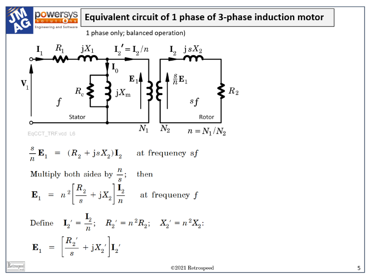
Fig. 3 Equivalent circuit of induction motor 2
The equivalent circuit thus has internal impedances, internal voltages and internal currents which cannot be measured individually in isolation, because measurements are possible only at the terminals. They can sometimes be brought out by special test conditions: for example, a DC measurement can be used to determine resistance independently of inductance. However, the internal parameters can be — and normally are — calculated in simulation exercises and other calculations. They are important in the theoretical understanding of the machine, and in its design and operation.
Equivalent circuits are sometimes found (either explicitly or implicitly) in IEEE and IEC standards, in connection with standard methods of test and even calculation. [6-8].
In the calculation of the parameters and performance of the equivalent circuit, an important question is how (if at all) to integrate the finite-element process.
We can identify three distinct approaches:
- Directly calculating the parameters of the classical equivalent circuit, especially the EMF and the inductances and flux-linkages, and their variation with the operating condition. Many of these parameters (for example, the Potier reactance) are not the natural outcome of a finite-element calculation per se, and for that reason we might wish to consider . . .
- Simulating the tests from which the equivalent-circuit parameters are traditionally obtained. For the classical wound-field synchronous machine these tests include the open-circuit characteristic (OCC), the short-circuit characteristic (SCC) and the zero-power-factor characteristic (ZPF). For the induction motor the simulations would include the no-load test at rated speed, and the locked-rotor test either at rated voltage or rated current. The numerical simulation would be used to produce ‘virtual’ test data that would normally be obtained by direct measurement in physical tests. That data would then be processed to extract the equivalent-circuit parameters, just as though it had been obtained by direct measurement.
- Calculating the performance characteristics directly without using the equivalent circuit. (Green dashed line in Fig. 1). The scope here is almost limitless. At the simplest level, a series of magnetostatic calculations can be used to calculate the open-circuit EMF waveform of a synchronous machine, from which the standard open-circuit characteristic is easily obtained, [1]. Much more complex calculations are possible and indeed normal in modern design engineering. They often go far beyond what is possible with equivalent-circuit models — to the extent that it seems likely that equivalent-circuit models may lose ground in the hierarchy of design tools. Before the days of advanced simulation technology, relatively simple field solutions were incorporated into some very complex extensions of equivalent circuit models, (e.g., [9] and [10]); but these have probably by now run their course and retain historical and archival value only. The scope of modern digital simulation extends into transient and dynamic performance, even at the level of the field equations, so equivalent-circuit methods are liable to be outclassed in this domain as well; but not rendered obsolete, because there are plenty of simpler cases to be calculated on a regular basis, and there remains much value to be gleaned from the interpretation of equivalent-circuit models.
It would be pointless to try to rank these approaches in terms of their usefulness, because all three of them are probably valuable in different circumstances. But it can be said that a serious study of all three methods will reveal a great deal about the structure of machine theory for all types of electric machine, and provide insight into the power of the finite-element method.
Notes
1 From Video No. 70. See also Videos 69-72
2 From Video No. 11
References
[1] Hendershot J.R. and Miller T.J.E., Design Studies in Electric Machines, Motor Design Books LLC, 2022, (Blue Book)ISBN-978-0-9840687-4-6, sales@motordesignbooks.com [2] Hendershot J.R. and Miller T.J.E., Design of Brushless Permanent-Magnet Machines, Motor Design Books LLC, 2010, (Green Book)
ISBN 978-0-9840687-0-8, sales@motordesignbooks.com [3] Bianchi N., Electrical Machine Analysis Using Finite Elements, CRC, Taylor & Francis, Boca Raton, 2005 [4] Molloy E. et al, The Electrical Engineer’s Reference Book, George Newnes, London, 1945 [5] Toliyat H. A. and Kliman G.B., Handbook of Electric Motors, 2nd edn., CRC Press Taylor & Francis, 2004 [6] IEEE Std 112 Standard Test Procedure for Polyphase Induction Motors and Generators (ANSI) [7] IEEE Std 115 Guide: Test Procedures for Synchronous Machines [8] IEEE Std 115A Standard Procedures for Obtaining Synchronous Machine Parameters by Standstill Frequency Response Testing [9] Jackson W. B. and Winchester R. L., Direct- and Quadrature-Axis Equivalent Circuits for Solid-Rotor Turbine Generators, Trans. IEEE, Vol. PAS-88, No. 7, pp. 1121–1136, July 1969 [10] Alger P.L., Induction Machines, Their Behavior and Uses, Second Edition, Gordon and Breach, New York, 1970