Explanation: Model-based Development
The fundamental efforts of JMAG for "model-based development (MBD)," which is starting to be applied to the development process as introduced previously, are outlined in this document. The new features of JMAG-Designer Ver.10.5, which was released on July 13th, for MBD are also introduced.
Aim of the Latest Version
JMAG is being developed recognizing the importance of MBD. The principle of MBD is to provide a highly accurate model as close to the real prototype as possible that can be used easily. Currently, JMAG is addressing MBD from two fronts.2
- MBD using JMAG-RT
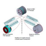
- MBD to link thermal, structural, and magnetic design
In this Newsletter, 1.,JMAG-RT, has been introducing the new features recognizing MBD which is realized by multiple plant models.
The accuracy and a high processing speed while being easy to used is demanded of models in system development including multiple ECUs because the logic consistency and synchronized speed between each ECU is evaluated. The solution that is recognized for this type of MBD is JMAG-RT. Whether the system can operate normally while processing abnormalities is evaluated assuming problems, such as sensor trouble or errors in operation occur. Whether or not the relationship between the parts as a system and whether or not the behavior of the system that is intended is achieved is also confirmed.
Accounting for Iron Loss in Motor Models
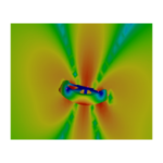
As described previously, the accuracy of the model is vital to MBD. The demands of PM motors are increasing for both higher efficiency and output while also requiring further miniaturization. The direction of development focuses on gaining output through higher rotation rather than increasing the torque using a larger heavy motor to satisfy these demands. This causes the ratio of the iron loss in the total loss to increase dramatically. The appropriate control for the drive of the motor needs to be used to realize higher efficiency considering this loss. The motor control becomes difficult when determining where to limit the iron loss in a region that is not normally used for a motor because the drive mode has a motor that is pulled along by the engine during operation(high rotation speed at a low load), such as hybrid vehicles, and the iron loss becomes the largest ratio of loss.
The PM motor model for JMAG-RT has realized a highly accurate model by accounting for nonlinear materials and detailed geometry, but the accuracy of the model is further enhanced because the iron loss characteristics can now be embedded. This information can contribute to the efficiency of the entire system because determining whether the loss is allocated to the motor or the inverter can be judged accurately by an even more precise motor model.
Furthermore, a simulation with more accuracy than linear models can be run because the iron loss characteristics are taken into account even for the IM motor model that has just been added.
An input terminal to account for the magnet flux and temperature dependency of the copper loss in the coil has been added to the behavior model. The temperature behavior can also be evaluated as a system which changes the motor characteristics by specifying the operational temperature in Simulink.
We talked with the engineer that developed the iron loss feature for the PM motor model in JMAG-RT, Katsuyuki Narita.
Q1. Why did you decide to add the iron loss feature to the PM motor model?
A1. Many customers where having problems where the torque and voltage did not match in simulations using JMAG-RT models, especially in the high speed region where the effects of the iron loss is large. In addition, there was a demand to be able to obtain the iron loss information to measure the temperature of the motor.
Q2. Why wasn't the iron loss previously available in the JMAG-RT model? Was it technically difficult?
A2. Modeling was conventionally undertaken considering parallel equality iron loss resistance, but the behavior of the loss when changing the current and rotation speed in the iron loss resistance had problems matching the measured results of prototypes and the transient analysis results of JMAG. For example, the iron loss is constant regardless of the rotation speed for a constant voltage in the conventional parallel equality iron loss resistance for a motor driven by an open loop voltage input. This is unnatural when you think of the iron loss for a permanent magnet motor.
We had been unable to find a way around this problem until we developed a modeling method that could fully use the iron loss information calculated in JMAG that we released.
Q3. What was the benefit of examining a modeling method concurrently while experimenting on a prototype?
A3. A good example is measuring the difference of iron loss by creating motors using different grades of electromagnetic steel sheet. The difference in the iron loss caused by the drive control method was also evaluated. Extremely valuable information was gained for the modeling of the iron loss because these results clarified the various behaviors of the iron loss. Of course, being able to verify the modeling method we developed against the actual measurements was also very important.
Q4. What were some of the aspects that made this project difficult to bring together and release as a product?
A4. I am sure this is obvious, but I had a lot of trouble getting the modeling of the iron loss usually obtained in an analysis using JMAG and the iron loss exported from the JMAG-RT model to match. I worked as hard as I could to get it right because the demand of our JMAG users was so high.
Q5. What did you think after you actually started using the model after succeeding in making it a product?
A5. I felt like I had resolved the problem of the torque being overestimated in the high speed region and not matching in the low speed region in control simulations for MBD. I hope that people will use it because it is also effective in measuring the temperature of motors.
Q6. What are some of the other enhancements you would like to make in the future?
A6. I am confident that the model accuracy has vastly improved because the core iron loss can be taken into account in this version we released, but the eddy currents that occur in the iron loss and magnets due to PWM modulation and spatial harmonics.
Adding an Induction Motor and SR Motor Model
Permanent magnet motors are not the only development challenges. There are still a larg number of induction motors being used throughout the world. Induction motors provide a wide-range of advantages such as a robust structure that doesn't need a special control to run as well as not requiring any magnets. Of course, better efficiency is expected from induction machines which requires the appropriate control. The cost for improving the performance of the control microcomputers of motors for powerelectroncis is decreasing in addition to the cost to improve VVVF and the vector control. These demands are why an induction motor has been added to JMAG-RT. The actual material properties and the magnetic circuit geometry are faithfully reproduced because the behavior model is generated from a JMAG magnetic field analysis just as the PM motor and stepping motor models.
A model of an SR motor which has gained attention as a motor without magnets has also been added. The origin of SRM itself is old, but the drive control is difficult because SRM have strong nonlinear characteristics with large inductance variations and they never became used widely because torque fluctuations are large.
The characteristics of the SRM have not changed, but these flaws can be overcome today by using more advanced magnetic design technology and drive control technology through electromagnetic field analysis. Motor engineers are gaining more interest in SRM because higher performance can be achieved. JMAG has added an SRM behavior model in the latest release. The SRM motor model contributes to comprehensively examining the control because the extreme current variations and torque can be reproduced authentically and the nonlinear characteristics of the inductance is modeled highly accurately.
These innovations will continue to be implemented into JMAG-RT improving the accuracy of the motor model while expanding the variations of models to satisfy the users needs.
Creating JMAG-RT Motor Models from JMAG-Express and Table Data
Inverter designers are not interested in the arrangement of the slot geometry and magnets, but see motors as inductance, resistance, and a power circuit. However, the ability to determine the motor design parameters or have a novice user create data to generate JMAG-RT motor models is thought of as being difficult. JMAG-Express is the tool that resolves this problem. A user inexperienced in motor design can create a model simply and then use the results that are obtained to generate a JMAG-RT motor model because the performance can be confirmed by creating that model easily in JMAG-Express. This means that a JMAG-RT motor model can be generated with ease even by an inverter designer.
A feature to create a JMAG-RT motor model from measured data such as inductance and torque has been added toallow users to create models from data tables. A motor model that is difficult to achieve by changing geometry, such as pushing the boundaries of the motor parameters, can be incorporated into a motor model to evaluate the control design.
These features allow everyone, not just motor designers, to be able to generate JMAG-RT motor models simply.
Using JMAG-RT Viewer to Share the Value of Motor Models
The above discusses the value of having the JMAG-RT motor models themselves, but some users have pointed out that they are difficult to use. Conventionally, a JMAG-RT motor model needed to be placed in a control simulator to see the actual JMAG-RT motor model, because JMAG-RT was originally a solution to increase the speed of control simulations.
A JMAG-RT Viewer capable of displaying the information in the JMAG-RT motor model (rtt file)has been developed to address this problem. The JMAG-RT Viewer is very useful for control designers that would like to review the motor characteristics, but it also allows motor designers to confirm their own motor characteristics because the JMAG-RT Viewer can create efficiency maps to examine the overall performance (T-N-η characteristics)as well as made the inductance(I-β-Ld/Lq)to display as the motor characteristics.
Conclusion
The above has focused on describing JMAG-RT based on the features that are available. These features further expand the range that JMAG can be used for MBD and we are confident it will contribute to system development. The next issue will introduce MBD using coupled analysis features.
dSPACE Interview
Currently, model-based development (hereinafter MBD) for the field of power electronicsAincluding motors, has yet to get into full swing, but a high percentage of the top ECUs that control motors have already incorporated MBD. Everyone presently using JMAG will eventually be implementing a MBD environment in the future. We talked with Takashi Miyano, Director of the Engineering Department at dSPACE Japan which provides the latest development tools to automotive ECU development and breaking new ground in MBD, to find out more about what is currently happening at the forefront of MBD.

Director of the Engineering Department at dSPACE Japan
Trends of MBD
Saying that automobiles have become a bulk of computers is not going too far as shown by the halted production of vehicles due to the microcomputer manufacturers for automobiles that feel victim to the earthquake in northern Japan.
Vehicles have to connect the ECUs utilized in engine units including the engine, power steering, and breaks as well as the ECUs built into amenity units like air conditioning and navigation systems.
A massive overall program is required to combine each of these ECUs that have their own control programs. The overall evaluation is also enormous because each independent unit needs to be confirmed in addition to examining everything at a system level.
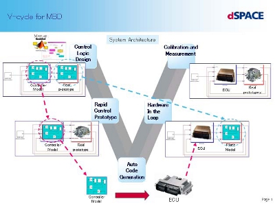
V-cycle for MBD
Forefront of MBD
When designing control systems, models of the controller (ECU) for the plant (control targets) models to be controlled are produced and adjusted. One MBD environment provided by dSPACE is the RCP, a prototype ECU capable of quickly supporting a controller model. The RCP includes a small stand-alone MicroAutoBox system and a RapidPro system with expansibility.
A second environment is a HILS used to construct the plant (controlled targets such as motors, actuators, and sensors). Both environments can control the actual control target in real time and verify the ECU in real time. The basic point is to automatically generate the C code for the ECU from the ECU control model created in the upstream processes in real-time simulations using RCP and HILS.
While MicroAutoBox has a calculation capacity that is quite capable of replicating an ECU, a control period of around 100MHz/100nsec can be achieved using an FPGA board when required for extremely high performance calculations in areas like power electronics-related modeling or image recognition. The MBD environments provided by dSPACE are MicroAutobox, a model to construct ECU and control programs that are built-in and the RaridProunit to construct the plant (control targets such as motors, actuators, and sensors). These interfaces are arranged so that a hardware-in-the-loop simulation can be configured. The fundamental point is to automatically generate the C code for the ECU from the control model of the ECU created in upper processes in real time simulations using MaicroAutoBox and PapidPro. MaicroAutobox has a calculation performance that can reproduce the ECU, but a control period of100 MHz/10 nsec can be achieved by using an FPGA board, which is required for extremely high performance calculations of modeling related to power electronics and image recognition.
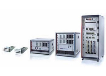
dSPACE HIL (Hardware-in-the-Loop) Simulation
Plant models, another vital key equivalent to ECUs in MDB, are refined by each user. The experience of the user is shown by what physical aspects should be embedded in the model. Evaluating the validity of a model is determined by rotating it through the V-cycle. Discrepancies in the model are found as a model moves to proceeding processes if the accuracy of the model is not sufficient because the system does not operate correctly, etc. If the cause of the discrepancies is the model, the problem is fixed and the V-cycle is repeated again.
In the case of automotive ECUs, one third of the source code is for diagnostics. It is necessary to confirm whether or not the control system is configured so as to prevent the system as a whole entering crisis mode as a result of a disturbance such as a broken wire, noise between a sensor and ECU, or plant failure-type damage.
For these checks, verifications are needed for various fault modes. Automatic testing using HILS is effective because as the system grows in size, the number of tests needed increases exponentially. Because real ECUs are naturally tested, plant simulation also has to be performed in real time.
Mr. Miyano's lecture about the extreme advantages of using MBD for ECUs and program development has been very informative. I asked Mr. Miyano to elaborate further for me as a designer close to plant design.
JMAG
This has been very informative about the amazing advantages of using MBD for ECUs and program development, but implementing MBD doesn't seem to affect the JMAG users who are closer to plant design. What are the benefits of implementing the MBD environment for plant designers?
Mr. Miyano from dSPACE
Demands for plants using MBD allow more specificity and detail. For example, there are requests like the torque variations of the motor need to be kept under X.XN-m. On one hand, the requirements may become stricter, but the sensitivity and the priority during optimization of the entire system becomes clear.
An optimal design for the components that meets system requirements (including over-spec review) is possible.
This final answer has cleared up any misunderstands I had.
MBD is something that engineers are hoping for if it has fair tradeoffs between the plant and control designers, and not whichever side has the loudest voice. This interview has really showed that the efficiency of development using MBD not only reduces the time of development, but also effectively shares information and the decisions that have been made.
Contact : dSPACE Japan Sales Department
TEL : 03-5798-5460
E-mail : info@dspace.jp
[JMAG Newsletter Summer, 2011]