Explanation: Model-based Development
In the last issue, we introduced the development intention of JMAG-RT that is one of the solutions for model-based development, resulting outcomes or the functions added with JMAG-Designer10.5. This time, entitling the issue 3 as the model-based development that gives an explanation of "Model-based development effectively connects with multi-complicated physical phenomena to each other" and this issue introduces the scene of model-based development includes is much more wide-range and it goes beyond coupling with the control circuit.
Reading this time's description may let you rediscover the idea of model-based development.
Current Status of the Coupled Analysis using CAE
Reality of CAE utilization
In today's research and development, utilization of CAE is very common, and it is used in wide-range development phase such as concept designs, further studies and reviewing of manufacturing process. From a viewpoint of physical phenomenon, however, the utilization of CAE does not go much beyond the purposes of upgrading and accelerating the design each physical phenomenon. For example, an engineer who needs to evaluate the structure aspect carries out structure CAE like measuring the actual machine using vibration testing machine and vend testing machine to evaluate the right and wrong of the design. Similarly, an engineer who needs to evaluate the electromagnetic force and loss of the motor utilizes the magnetic field CAE like measuring the output characteristics by motor-bench testing or measuring using the LCR meter.
A concern that comes up in this situation, a structural engineer and a magnetic field engineer may evaluate different models each other. Each engineer must comprehensively judge how does the improvement measure conducted in his own task effect to other tasks, or if total optimization is done. Viewing the different model, however, one sometimes makes a wrong synthetic judgment. See Fig. 1.
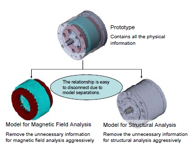 Fig. 1 Relationship between the Actual Machine and Analysis Model
For example, when considering the countermeasure for the motor vibration that occurs resonance at 1000 Hz, it is very difficult to judge if conduct only one of the countermeasure of magnetic field or structures, or both of them simultaneously. In case conducting the countermeasure that reduces the frequency individually results in again the same resonance frequency at 800 Hz for both of the magnetic field or structures, which are terrible. Considering these two countermeasures simultaneously, such situation does not occur, but the concurrency that is expected to CAE will not be realized. Therefore, interoperating with two different models requires extremely careful management.
Needless to say, all the physical behavior can be checked with the actual products and prototypes, so that will be a help to avoid the engineer of each field to view the different models that will be a problem with CAE. Structural countermeasure enables you to check the magnetic influence instantly. However, creating prototypes forces you to encounter the hard reality of the necessity of lots of time and a large cost.
Insufficient Performance of the Coupled Analysis
Current market released version of coupled analysis simulation successfully realized evaluating the same models linking the same models to each other with multiple themes "in theory". Actually, however, delicate and minute works just like appropriately converting physical quantity of the related model data or adjusting the link timing are required for actual operations, and, in many cases, such works are realized by analysis specialists' advanced technologies and mental strength.
In other words, no user-friendly coupled analysis simulator that lots of front-line engineers can utilize over the entire process of the daily development unfortunately exists. It's an unfortunate reality.
On the contrary, overcoming this problem enables CAE to make a contribution to improvements in development efficiency.
Dealing with the Model-based Development Links Multiple Physical Systems Effectively
What CAE should aim to
Just imagine the role CAD plays in machine designs. The greatest benefit of CAD is not that easy line drawing on the computer but multiple designers can share the information and discuss design studies simultaneously. This benefit enables lots of designers to cooperate, and mounting various functions in the limited space in a short time, and also realizes an excellent design. CAD model includes the information on dimensions, materials, and design know-how.
The target direction of the model-based development is incorporating information on physical behavior to this shared information. The model-based development requires the models that take part in developments to enhance the information traffics, and it makes a contribution to the more smooth communication between involved contact personnel and departments. Needless to say, the ideal model that is used in model-based development is "A model that has all the characteristics of actual machines" and "Easily extract the characteristics". See Fig. 2.
For example, a control technician who is in charge of developing motor drive systems uses the models with being interested in torque characteristics and response to carry out design evaluation of control logic or using device. Concerning magnetic saturation or temperature distribution, however, its influence is only indirect, so control technicians have little interests of that. After handing off the model to a thermal system designer, it will be utilized for thermal system study and evaluated from the view of heating design.
If each person in charge utilizes control models or thermal models, they possibly check the different points, but a model includes all the characteristics and the information is easy to obtain, and information sharing is easy and it leads to improvement of development efficiency or product quality.
Linking multiple analyses must be done easily
Actually, it is not important to figure out the causal connection of complicated physical phenomenon in design works. In fact, actual machine includes the causal connection of complicated physical phenomenon at the point of being object. According to the entered input, outputs the response on the basis of the physical causal connection. An actual machine that is an anorganic substance has no way to its own causal connection, and it is easy for evaluation engineers to make a contribution to problem resolution if they know the causal connection, but they can evaluate good or bad if they do not.
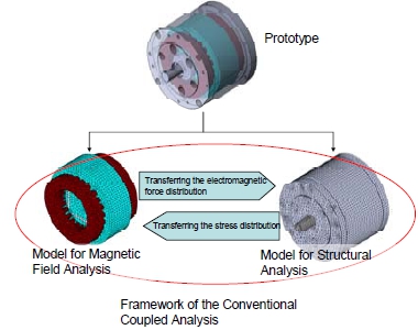
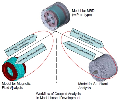 Fig. 2. Framework Change of Coupled Analysis by Introducing Model-based Development
(Upper: Conventional Coupled Analysis , Lower: Coupled Analysis under Model-based Development Environment)
After all, the major cause of complicated physical phenomenon is insufficient performance of CAE that cannot express many faces. In order to make model-based development the substitution of actual machine evaluation, you should not force users to understand causal connection.
Current Achievement
JMAG give emphasis to basic performance like carrying out highly accurate magnetic field analysis in high speed, and also aims to be ready to utilize its results versatilely in model-based development. It is impossible to reach the goal at a bound, so JMAG is going forward step by step.
Our action assignment at this point is to enhance JMAG's performance so that the machine designer can carry out structural analysis based on the magnetic field analysis results obtained from JMAG using his familiar structural analysis software without learning the JMAG operation. Similarly, another our assignment is enabling JMAG users to carry out magnetic field analysis based on the structural analysis results on his familiar JMAG without learning the operation of structural analysis software. Concerning these points, I would like to introduce the tasks we have already achieved and the ones we are realizing in the near future.
Linking to Abaqus
As I always explain, we have worked hard on enhance the linkage performance to the structural analysis software "Abaqus" manufactured by SIMULIA, and it is widely used in the filed of nonlinear structural analysis. At this point, it is possible to directly read the result file of electromagnetic force distribution obtained by JMAG on Abaqus, and input electromagnetic force to carry out nonlinear structural analysis. Similarly, it is possible to input the eddy current loss obtained by JMAG to perform the thermal analysis. On the other hand, it is possible to directly read the stress distribution file obtained by Abaqus on JMAG, and to perform the magnetic field analysis taking account of the stress magnetic properties. This enables structural analysis engineer to easily utilize the analysis results that is in charge of the electromagnetic field analysis engineer, and of course vise versa, so much higher information sharing is realized.
Also, we are developing a function to maintain linkages even in the phenomenon with model deformation that Abaqus is good at. It is going to be the function that can evaluate a complicated physical phenomenon with shape deformation like electromagnetic forming.
Linking to LMS Virtual.Lab
We plan to enhance the link features with Virtual.Lab manufactured by LMS International who offers solutions for vibration noise analysis. So far, the feature only outputs the data in Nastran format, it is going to directly read the result file of electromagnetic force distribution obtained by JMAG on Virtual.Lab, and to input electromagnetic force to perform vibration noise analysis.
In the development of electrical devices, requirement of vibration noise reduction is getting higher, so we understand we have the responsibility of offering solutions in this field.
In Closing
We of course keep enhancing the basic features on the electromagnetic field analysis using JMAG, and also plan to make a contribution to the model-based development by strengthen the linkage so that the result can be easily utilize on the other simulation software. It's "OPEN" that has the task to embody it, and we indicate it in the development concept.
Future dream, concept on Virtual Test Bench
We are releasing Virtual Test Bench (from here on VTB) on the next version. VTB has two roles. The first one is the function that easily gives the causal connection to models. It is setting physical causal connections such as of course the magnetic field characteristics and also temperature dependency and stress dependent and so on.
The second one is the function that easily evaluates the magnetic field characteristics. Without attending training sessions or seminars, we plan to prepare the environment of easy evaluation tasks for structural or thermal system designers.
At the first time, an electromagnetic field analysis engineer needs to design the modeling policies or evaluation flows, but we aim to make it possible to utilize them easily by other than electromagnetic field analysis engineers after designing them.
After realizing this, for example, in a case that a structural designer changed the clearance of shrink fitting of stator core, it is possible to perform the structural design while checking how influence appears on the output characteristics of the motor.
Even such accurate analysis as an electromagnetic designer cannot be realized, but you can check the effects of the magnetic field boundary done by design changes that the machine designer made with learning "only few" JMAG operations.
These facts match with the model-based development aim of easily revealing complicated physical phenomenon.
[JMAG Newsletter Fall, 2011]