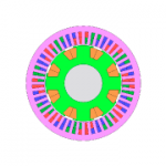
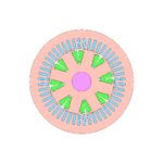
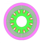
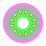
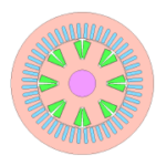
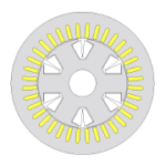
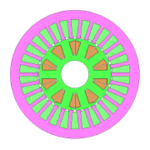
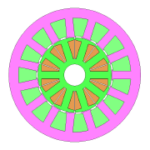
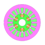
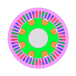
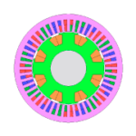
Wound-field and electrically-excited synchronous motors (WFSM/EESM) are given attention as traction motor that requires high efficiency in a wide operating range. Although high efficiency can be expected in the low torque range compared to permanent magnet synchronous motor (PMSM), there are specific issues in the design process, such as cooling measures due to the increase in losses, and controls that also take into account the field. JMAG enables the design and verification of WFSM/EESM even by considering the aforementioned design issues.
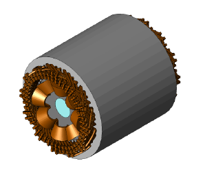
Characteristics of WFSM/EESM
Ld, Lq
- Reluctance torque is generated at the lagging phase (<0) since it is a normal salient pole (Ld>Lq) motor
- Electromagnetic field analysis is effective since characteristics abruptly change with saturation by the field current
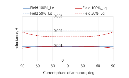
LdLq characteristics by the field current
Efficiency map
- The possibility of the efficiency of WFSM/EESM exceeding that of PMSM in the low torque range, when compared to PMSM of similar size and build, can be observed
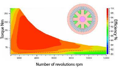
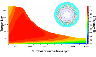
Efficiency map of WFSM/EESM(Left) and PMSM(Right)
The possibility of the efficiency of WFSM/EESM exceeding that of PMSM in the low load range, as separated by the red-dotted line, is observed
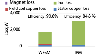
Efficiency and loss breakdown
- Checking the difference in efficiency and loss breakdown of WFSM/EESM and PMSM by taking into account the losses during the operation of an inverter by combining the use of a control circuit
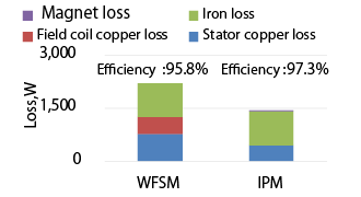
- Characteristics indicating high efficiency at low load and high RPM can be observed, even by taking into consideration the copper loss of the field
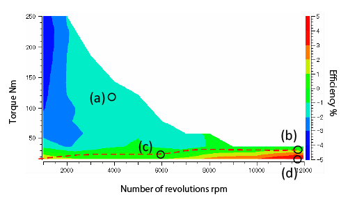
Difference between the efficiency (%) of WFSM/EESM and PMSM
Efficiency is compared by taking the difference between both motors in the entire efficiency map range
Efficiency > 0 in the right axis indicates that WFSM/EESM has higher efficiency
(a)
(b)
(c)
(d)
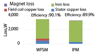
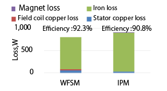
Breakdown of each loss at operating points (a) – (d) and respective efficiencies
Indicating that iron loss at high RPM and low load is reduced and characteristics of WFSM/EESM being able to achieve high efficiency
On-demand Webinar
JMAG solution
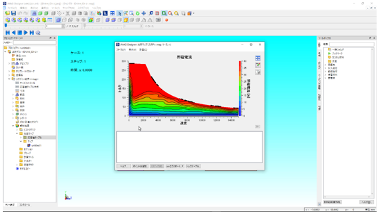
Characteristic evaluation, efficiency map
- The efficiency map (Speed Priority Mode) creates an efficiency map by extracting maximum efficiency at each operating point from an efficiency map for the respective field currentTry with the latest, V22.1
- Characteristics such as Ld and Lq can be obtained and can be used as parameters for the control circuit
JMAG Function Videos
Application Catalog
Achieving more accuracy for losses by the use of controls
- The efficiency map (Accuracy Priority Mode) is combined with a control circuit and creates an efficiency map that accounts for losses during the operation of an inverter
- Current vectors and control parameters use an efficiency map and characteristic values obtained in Speed Priority Mode
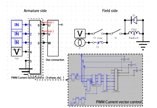
Control circuit
Run the control circuit simulation by using preinstall operator components in the circuit on the armature side
Leaflet
Thermal design
- Preinstall operator components can be used for a representative cooling type in a thermal equivalent circuit in JMAG
- Even for Engineers designing electromagnetic products, temperature evaluation can easily be started just by specifying parameters related to the cooling method
Ex: Study of the cooling effect of field winding by spray cooling and cooling jacket
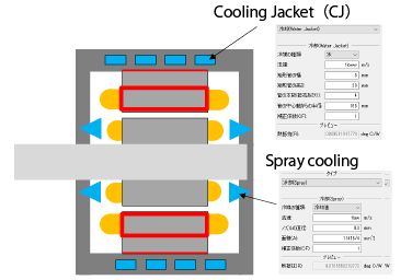
Cooling method and modeling
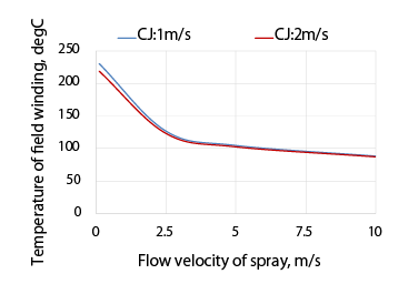
Temperature of the field winding when changing the flow velocity of coolant
It can be seen that the flow velocity of spray around 4m/s is necessary in order to bring the temperature down to below 120℃ in this example. It can be seen that it is necessary to directly cool using the spray since the effect on field winding temperature is small even by doubling the flow velocity in the Cooling Jacket (CJ).
Application / Solutions
Integrating MIL/HIL
- Compatible with the JMAG-RT model, a high-fidelity plant model based on FEA which is equivalent to a prototype/actual machine
- It enables a highly-reliable control circuit simulation by using the JMAG-RT model
Ex: Comparison of characteristic evaluations using the JMAG-RT model and dq model, which is a classical plant model
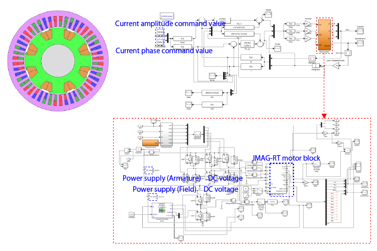
WFSM/EESM (Left) and Control circuit diagram in MATLAB/Simulink(Above:Main circuit, Below:Sub-circuit)
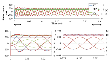
Time history of field and phase currents
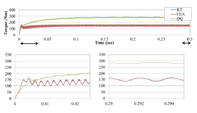
Time history of torque
Comparing the analysis results for FEA, JMAG-RT, and dq models on currents and torque characteristics when applying 20A to armature and 10A to field respectively, as command current values. When checking time histories of field and phase currents, control based on the command value is taking place at the end however, there is a discrepancy at the beginning for the dq model. Furthermore, the discrepancy between the dq model and FEA is large for torque characteristics, and a satisfactory level of accuracy for a plant model can be expected by using the JMAG-RT model. A high-fidelity plant model based on FEA is useful since WFSM/EESM have their characteristics largely affected by the difference in magnetic saturation depending on the amount of field current.
It is possible to utilize the RT model of WFSM/EESM for “function verification of abnormal system” and “performance verification” based on the fact that the accuracy of FEA and RT are equivalent for the current control of a normal system.
Application Catalog
JMAG-RT Model Library
Case study
User case

Performance Calculation of Wound Field Synchronous Motors as the Traction Motor for Vehicles
Assuming application for automotive traction, torque/output characteristics and efficiency for wound-field motor categorized as 100kW class are calculated in JMAG, and the practicality as a traction motor compared to the PM motor is examined.
please contact us.

