Contents
1. Environments That Take Stress into Account
2. Iron Loss Calculation Approach Accounting for Stress Using JMAG
3.Challenges
4.Real Examples
5.Conclusion
6. References
1. Environments That Take Stress into Account
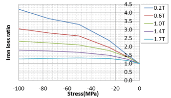
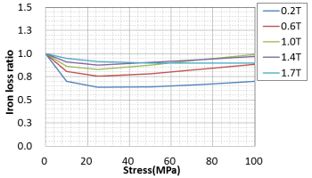
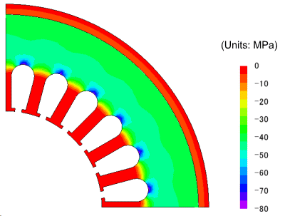
Increasing the accuracy of an iron loss analysis for a magnetic field analysis poses challenges. With conventional iron loss calculation methods, the iron loss characteristics of electromagnetic steel sheet materials that were measured beforehand with methods such as the Epstein method are used to estimate iron loss in machines. However, it is known that iron loss increases more in electromagnetic steel sheets inside actual electric machines than it does than from various factors. Stress can be cited as one of the factors. In figure 1, an example shows how iron loss in an electromagnetic steel sheet is affected by stress. Electromagnetic steel sheets in physical machines receive stress due to shrink fitting / press fitting the frame, fixed lamination from caulking / welding / bolt tightening, and temperature distribution (thermal stress). For example, the results of performing a structural analysis on compressive stress generated by press fitting the frame of a stator core in a motor is shown in figure 2. Compressive stress of 30 MPa or more is applied to the back yoke section, and the impact on iron loss is great when considering the rate of increase in figure 1. Therefore, it becomes clear that this factor cannot be ignored. The effects of stress must be accounted for in order to perform a highly reliable loss evaluation.

(a) compressive stress

(b) tensile stress
Fig. 1 Impact on iron loss due to stress (35A360)
The impact of compressive stress is great, and compressive stress of several tens of MPa increases iron loss by more than 2 times.

Fig. 2 Compressive stress when press fitting a frame in a stator core
The smaller the value (absolute value is large for negative values), the stronger the effects of compressive stress.
The bottom section of slots are the strongest, and it also occurs in the back yoke section
2. Iron Loss Calculation Approach Accounting for Stress Using JMAG
Fig. 3 shows the procedure for iron loss calculation taking stress into account using electromagnetic field analysis and structural analysis.
- Obtain the stress distribution with a structural analysis.
Calculate stress caused by press fitting / caulking / welding / bolt fastening, and temperature distribution - Set the stress dependent magnetic properties (B-H curve).
Like iron loss, the field changes due to stress because the magnetic properties (B-H curve) are also affected by stress. A B-H curve is set for each stress as shown in figure 4. - 1. Stress distribution obtained in steps 1 and 3 are mapped, and a magnetic field analysis is performed.
- The effects of stress are reflected in the iron loss calculation
As shown in figure 1, the effects of compression stress or tensile stress differs. As a result, magnetic flux density obtained in a magnetic field analysis separates in the direction of principal stress I (tensile stress) and principal stress III (compressive stress). An evaluation of iron loss accounting for the stress of each direction is performed, and they are added together to evaluate the entire iron loss.
You need to sign in as a Regular JMAG Software User (paid user) or JMAG WEB MEMBER (free membership).
By registering as a JMAG WEB MEMBER, you can browse technical materials and other member-only contents for free.
If you are not registered, click the “Create an Account” button.
Create an Account Sign in


