*Please prepare a license ID and password for the license administrator.
*It is different from the service for JMAG WEB MEMBER (free membership). Please be careful.
Overview

Collaborative design is difficult because the controls and motor are designed independently. However, it has become necessary to resolve challenges through high-accuracy simulations at the beginning of the development process in order meet demands for more advanced motors. An effective way of achieving this is for the simulations to be performed while collaborating on the motor design circuit/control designs.
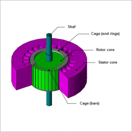
An induction motor’s characteristics are influenced by leakage reactance and resistance, including resistance on the secondary side. The resistance on the secondary side is affected by the skin effect, so the finite element method (FEM) needs to be used to obtain the distribution of the secondary induced current. With JMAG, it is possible to use a magnetic field analysis to obtain the resistance and leakage reactance, and to create a model of an induction motor, as well. Incorporating this motor model, called a “JMAG-RT model,” to a circuit/control simulator makes it possible to use JMAG-RT to run a linked simulation with it.
This Application Note explains how to use the JMAG-RT to create a JMAG-RT model of an induction motor, import it to a circuit/control simulator, and run an induction motor line start simulation.
Rotation Speed Waveform

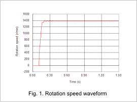
The rotation speed waveform when starting the induction motor is indicated in fig. 1.
From fig. 1, it is apparent that the motor accelerates rapidly at the initial start-up and moves to a more steady acceleration while transitioning to a steady state.
From fig. 1, it is apparent that the motor accelerates rapidly at the initial start-up and moves to a more steady acceleration while transitioning to a steady state.
Torque waveform

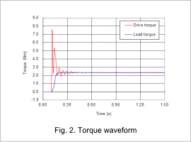
The waveforms of the drive torque and load torque when starting the induction motor are indicated in fig. 2.
From fig. 2, it is apparent that a large drive torque is generated at initial start-up. Furthermore, the drive torque becomes almost constant as the load torque balances out in the steady state.
From fig. 2, it is apparent that a large drive torque is generated at initial start-up. Furthermore, the drive torque becomes almost constant as the load torque balances out in the steady state.
Current Waveform

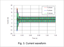
The current waveform of the stator coil when the induction motor starts is indicated in fig. 3.
Fig. 3 shows that an extremely large current is produced during the initial start-up. This is because the back electromotive voltage at initial start-up is small and almost all of the power supply voltage is applied to the stator coils. At a steady state, the three-phase AC has an amplitude of less than 5 A.
Fig. 3 shows that an extremely large current is produced during the initial start-up. This is because the back electromotive voltage at initial start-up is small and almost all of the power supply voltage is applied to the stator coils. At a steady state, the three-phase AC has an amplitude of less than 5 A.


