Overview
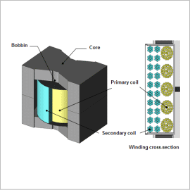
Power supply circuits require designs that limit the cost of operation but as portability becomes a focus and harmonics of switch frequencies become common, heating of the winding becomes an issue. To increase pressure resistance, there are times when gap is necessary for the core; however, with magnetic flux fringing near the gap, local heat generation may occur due to proximity effects in the winding. Local heat generation will not only drop the conversion efficiency of electrical power but it will also cause degradation in the insulating film so it is important to control it as much as possible.
The Litz wire is one wire separated into multiple thin wires, painted with enamel film, and twisted together. Separating one wire into multiple thin wires controls the concentration of current due to the skin effect. By adding twisted structure to the bundle wire, it is expected that the current flows more evenly, and local heat generation is controlled.
This document introduces confirms the effects on copper loss due to the presence or absence of a twisted structure in the winding regarding the copper loss that occurs in the small switching transformer structured with PQ cores.
Current Waveform, Copper Loss Waveform
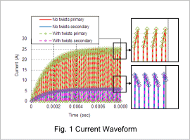
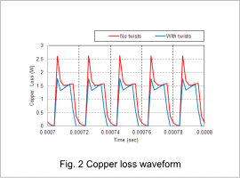
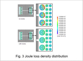
Fig. 1 shows primary and secondary current waveform depending on whether twisted wire is used or not, and Fig. 2 shows primary copper loss waveform. Fig. 1 shows that it has reached the steady state after 0.0006(sec) and whether or not it has twists, there are responses at approximately the same times. Also, Fig. 2 confirms that the average value of copper loss in winding for the primary winding has dropped by approximately 26(%) for the case with twists compared to the one without. It is assumed that with local flux linkage inside the winding dropping due to twist effects, local biases of eddy current caused by time variations have been resolved.
Joule Loss Density Distribution
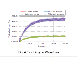
Flux Linkage Waveform
