Overview
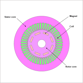
Optimization that uses FEA is effective in satisfying these strict requirements. Parameter optimization that can change dimensions to parametrics depends on the topology of the initial geometry that is the optimum geometry. Topology optimization capable of making significant changes to part layout can make changes to topology and perform searches in wider design spaces.
In this example, rotor core maximum stress and radial direction maximum displacement in the radial direction are set to certain values or less, and rotor geometry is designed that minimizes the torque ripple and maximizes the average torque value. Sensitivity analysis is then performed afterwards.
Optimization Conditions
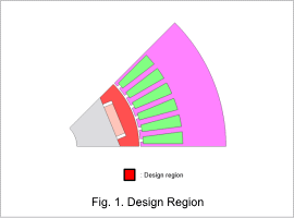
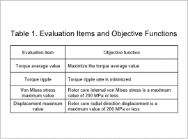
Fig. 1 shows the design region, and Table 1 shows the evaluation items and objective function.
Fig. 1 shows that the design region is situated near the magnet and the gap which are considered to have a large effect on von Mises stress and torque.
Optimization Results
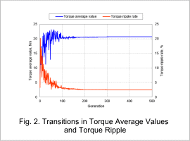
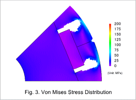
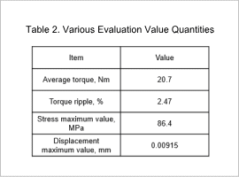
The transitions in the torque average values and torque ripple rates for the best cases of each generation are shown in Fig. 2. The von Mises stress distribution for the best cases throughout all generations are shown in Fig. 3, with various quantities shown in Table 2.
A state of convergence where torque average values grow larger with each generation and torque ripple rates grows smaller can be confirmed
In is understood that in the best cases, results that satisfy von Mises stress and radial direction displacement constraints are obtained.
Sensitivity Analysis Results
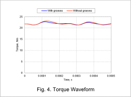
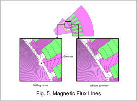
Torque waveforms and magnetic flux lines are shown in Fig. 4 and Fig. 5 respectively for when grooves are present and absent in the rotor core surface for the geometry obtained with optimization. Unlike case optimization, no smoothing is performed for the boundary faces between materials, meaning that results with grooves differ from optimization results.
Although optimization uses the grooves because the torque ripple rate improves when the grooves are present, the effect is rather small, and no significant changes to magnetic flux flowing from the rotor to the stator teeth can be observed. As such, it is thought that even an absence of grooves is acceptable for the design.
