Overview
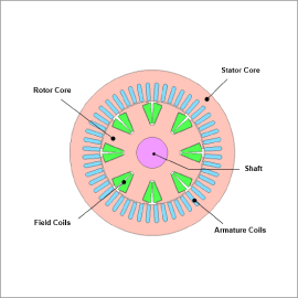
As one type of open-end winding motor drive system, common power supply systems produce flyback voltage—known as zero-sequence current—between the bus and windings connected to two inverters. The control system must take into account the zero-sequence current in dual inverter drive systems because the zero-sequence current increases the torque ripple and losses.
JMAG can generate plant models (JMAG-RT models) that can take into account magnetic saturation, spatial harmonics, and zero-sequence currents that occur in open-end winding motors. Control/circuit simulations embedding plant models enable coupled simulations that consider not just the motor characteristics but also the drive control.
This case study runs a circuit simulation of an open-end winding motor drive system that switches from using a single inverter to dual inverters during operation in order to mitigate zero-sequence current and control the target torque.
Control Circuit
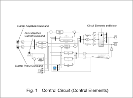
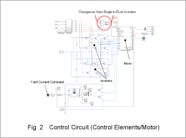
The control elements of the control circuit are presented in Fig. 1. The circuit elements and motor are illustrated in Fig. 2. The current amplitude and current phase utilize command values, while the motor receives the voltage command via the inverters. The target torque is 30 Nm at low load for the first 0.03 sec but rises to 150 Nm at high load from 0.1 sec.
The command values are 41.4 A for the current amplitude, 21.6 deg for the current phase, and 11.8 A for the field current up to 0.03 sec, which increase to a current amplitude of 106.6 A, current phase of 3.1 deg, and field current of 29.8 A from 0.1 sec.
Control parameters other than the current amplitude and current phase remain constant.
The drive system switches from using a single inverter drive to dual inverters at 0.05 sec.
Single Inverter Drive
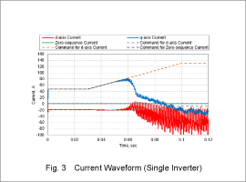
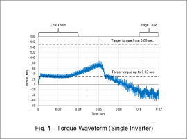
The current waveform is presented in Fig. 3 and the torque waveform in Fig. 4 when the drive system does not switch from a single to dual inverter drive when the load increases.
The motor drive system applies a current as specified by the current command at low load (up to 0.03 sec) and achieves the target torque value, but the current at approx. 0.05 sec cannot keep up with the command value as the load increases. This prevents the motor drive from reaching the target torque value.
Changeover to Dual Inverter Drive
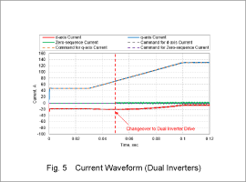
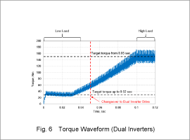
The current waveform is presented in Fig. 5 and the torque waveform in Fig. 6 when the drive system does switch from a single to dual inverter drive as the load increases.
The current adheres to the command value, and the motor drive reaches the desired torque value. This is because the dual inverter drive system is able to increase the applied voltage. The dual inverters do produce zero-sequence current when in operation, but the motor system restricts the zero-sequence current to approx. 0 A.
