 Fig. 1
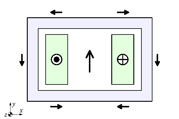
Eddy-currents flow in closed loops. It follows that for any physical device in which eddy-currents arise, only a three-dimensional analysis can be complete. Any two-dimensional analysis will be incomplete, because it neglects the end-effects which represent the closure of the current-loops. We can see this in Fig. 1 even without eddy-currents. A twin busbar carries current in the z-direction through an Aluminium duct over a distance much longer than the width or height of the busbars. Fig. 1 is a transverse cross-section at some point that is so remote from the ends that we assume the end-effects to be of no significance, leaving a two-dimensional analytical model. Parameters such as resistance, inductance, flux-linkage, and losses are calculated per unit of length in the z-direction, and multiplied by the overall length of the duct (often without any correction for end-effects). Within the transverse plane of the 2-dimensional model, the vector potential A has only a z-component; and the same is true for the current-density J — not only in the conductors but also in any eddy-currents that may be induced in the duct walls. The flux-density B has both x– and y-components, and flux-lines form closed loops in the transverse plane (by Gauss’ law). It is a useful exercise to draw a few flux-lines by hand.
The black arrows in Fig. 1 are vectors representing the instantaneous flux-density B at several locations, with currents in the two conductors in the directions shown. It makes an interesting exercise to build this model in JMAG with DC, and plot the flux-lines and the coloured contour plot showing the entire field in all its detail. (See Videos 42 and 43).
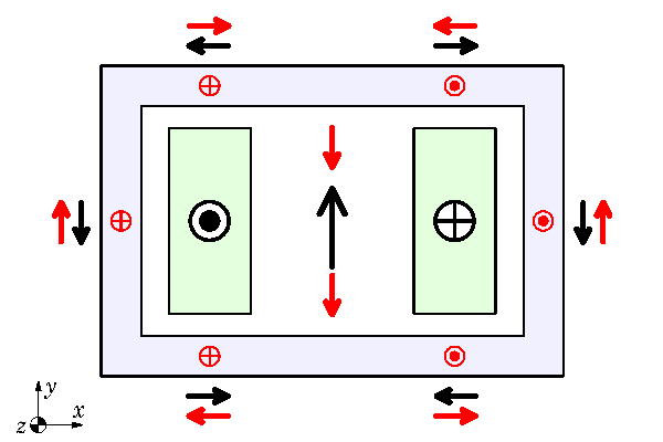 Fig. 2
The contrast between such finite-element images and the black vectors in Fig. 1 could not be more striking, and yet we can still get helpful engineering insights from the hand-drawn vectors. Before the days of finite-element analysis, these insights were important in helping to deal with problems that could not be computed easily — or at all — by classical analytical methods. The two-dimensional problem in Fig. 1 can be calculated adequately by classical analytical methods under DC conditions, but for AC conditions with eddy-currents in the duct walls we would need an infinite series of spatial harmonics in both x and y — a laborious and error-prone process. Three-dimensional problems were (and still are) beyond the scope of practical classical analysis.
The insights we get from the hand-drawn B-vectors can be gleaned from finite-element solutions, of course : but let’s go through the exercise of considering eddy-current effects without the help of a finite-element solution. Then it is suggested to try such a model yourself with a frequency analysis in JMAG, to see if you can draw the same conclusions.
So in Fig. 2 we have AC conditions and the frequency is high enough to induce so-called inductance-limited eddy-currents in the duct walls. ‘Inductance-limited’ means that the impedance controlling the eddy-currents is essentially inductive, while the resistive part of the impedance is relatively insignificant. This happens naturally at higher frequencies and is often associated with the condition where the skin-depth in the conducting regions is less than the thickness (in this case, the thickness of the duct walls). We will not study the skin-depth formula here because, by itself, it is not a sufficient measure of the condition of the eddy-currents — the effect of the geometry is also significant. So we will simply assume that the eddy-currents are inductance-limited.
Inductance-limited eddy-currents produce a reaction field that tends to oppose the applied field. We can use this principle as a basis to draw the red dots and crosses representing the eddy-currents, and the red vectors representing their reaction field, as in Fig. 2.
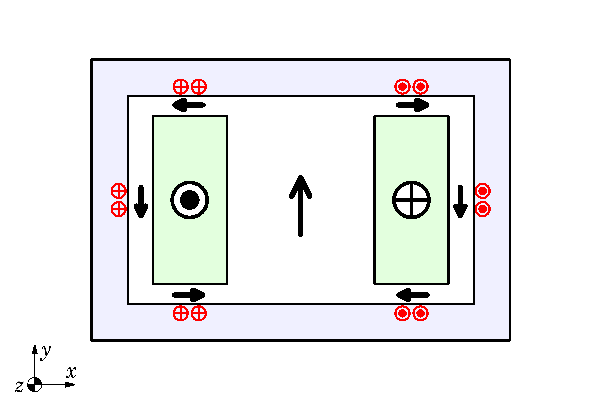 Fig. 3
The applied field represented by the black vectors is only partially cancelled by the red vectors produced by the eddy-currents. To cancel the applied field completely, the eddy-currents would need to be in the same physical locations as the main conductors and they would need to be in anti-phase. Neither of these conditions is satisfied (particularly the first), and so there is a residual field of flux, some of which runs round the duct wall.
Now at this point I’m going to borrow from the old language that we used to use in describing such effects, by saying that the eddy-currents don’t like to see that flux running round the duct walls and so they react in such a way as to expel it. We therefore have loops of eddy-current in the duct walls, with ‘go’ and ‘return’ distributed across the thickness through the duct walls forming ‘coils’ or solenoids aligned in such a way as to annul or expel the applied flux from the conducting walls. These secondary eddy-currents, if you will, are superimposed on the primary eddy-currents in Fig. 2, to produce the redistribution of eddy-currents depicted in Fig. 3. Behold the skin-effect in the duct walls, where the eddy-currents crowd towards the inner edge and are attenuated near the outer edge.
The resultant field of flux is now represented by a new set of black vectors which are entirely confined within the interior of the duct. It is a useful exercise to draw some complete flux-lines by hand, joining the black vectors end-to-end. Since the flux is entirely confined within the duct, we can say that the duct is acting as an eddy-current shield, which in effect prevents the flux of the main conductors from escaping into the space outside the duct.
What is more, the black vector in the middle of Fig. 3 is smaller than the one in Figs. 1 & 2, because the total flux-linkage of the circuit comprising the two conductors is reduced. The eddy-currents produce what we call a dynamic reduction of the circuit inductance. Indeed the eddy-currents can be represented by means of a ‘secondary’ circuit coupled to the ‘primary’ circuit formed by the main conductors, and then the primary inductance is dynamically reduced to what we call the leakage inductance. (See Videos 37 – 40).
Was this helpful, or was it completely crazy? The attribution of human characteristics to inanimate objects is, I believe, called anthropomorphism. One might imagine that in our serious professional technical comings-and-goings there is no place for stating that
“the eddy-currents don’t like to see that flux running round the duct walls”.
But engineers have a sense of humour and a way of explaining things, and that statement serves to avoid several pages of differential calculus. It is also perfectly and literally true in its effect, which is that
“they react in such a way as to expel it”.
How do we know this? Well, we can discover it by measurements in the laboratory — and again it is suggested as an interesting exercise to devise experiments to verify all the phenomena we have discussed, or as many of them as possible. We can also discover it by exercises with the finite-element method. This is attempted in Video 44, which also fills in many steps in the ‘black-and-red-vector’ story that we have skipped here.
The behaviour of eddy-currents is of course much more complicated than we might suppose from amusing ourselves with black and red vectors. It extends to related effects such as skin-effect and proximity-effect in conductors, both of which are crucially important in the design of windings for high-performance electric machines. Even in simplified two-dimensional models, these problems are orders of magnitude too complex for classical analysis. When we have a problem that cannot be approximated by a two-dimensional section, (such as eddy-current losses on the rotor of a brushless permanent-magnet motor) a full three-dimensional solution is called for. In such cases the extraordinary power of numerical analysis is brought into focus in the most spectacular way. The general notions of eddy-current reaction and the dynamic reduction of effective inductance are still essential guides to interpretation; but the behaviour of eddy-currents and related fields can become very complex especially in local details, and we probably have to be content with the hand-drawn vectors only in the simplest physical configurations.
Note that although I have mentioned hand-drawn flux lines, I have not drawn any in Figs. 1 – 3. Under DC conditions in two dimensions they can be drawn with confidence to give a simplified representation of the flux pattern. Under AC conditions it may appear to be theoretically feasible to draw a pattern of flux-lines at one instant; but in general the phase of the eddy-current density is not uniform, and this impairs or even destroys the simple physical interpretation associated with DC flux-lines. If the eddy-currents are completely inductance-limited — that is, in anti-phase with the exciting current at all points — then the flux-lines become meaningful again, and this condition is implicit in the foregoing discussion (as stated at the beginning). But this is an extreme condition, approached (but never perfectly achieved) at the highest frequencies. With a finite-element solution there is always the temptation to draw “flux-lines” of the RMS value of the flux-density, but these are not true flux-lines in the classical sense associated with Ampère’s law and Gauss’ law. Instead they are contours of constant RMS flux-density — still meaningful as an indication of the generation of the eddy-current Joule loss distribution; but since that loss distribution can itself be plotted, the value of these AC “flux-lines” is diminished. This may explain why we do not normally use flux-lines to represent AC solutions; in three-dimensional solutions they become meaningless anyway, because they no longer represent the boundaries of “flux-tubes” (a quaint concept that is sometimes used to prop up their use in two-dimensional problems). The contour plots of flux-density and current-density remain perfectly rigorous; but if RMS values are used, as would normally be the case, all phase information is lost. That might restore a little justification for the anthropomorphic discussion of the black-and-red dots, crosses, and vectors in the foregoing. While the old classical analysis methods are sinking without trace, some of the insights and interpretations remain useful, and we have the task of retaining them and renewing the art of distilling them from finite-element solutions.
Complicated? Yes, eddy-current problems are complicated — very complicated. Thank goodness we have finite-element methods to solve them.
Afterthought : If you are sitting with your friends and colleagues in a beer-bar or a sushi-bar, or anywhere where there are table-napkins, and you are discussing the finer points of eddy-current behaviour, the diagrams you draw on those table-napkins may be similar to Figs. 1 – 3. Indeed in most cases there will be no labels, just as there are no labels in Figs. 1 – 3. That is also the case with the flux-plots we see in finite-element solutions — no labels. Is that a bad thing or a good thing? It’s a good thing, because when we are looking at these diagrams we are focussing on the meaning and interpretation, and we don’t want the diagrams cluttered with labels. In the discussion surrounding the table-napkin drawings, the components in the drawings will be identified verbally and vocally, and the whole process of contemplation will be enriched by the auditory experience of discussion. I hope this Diary will encourage discussion among friends and colleagues.
Further reading
McLachlan N. W., Bessel Functions for Engineers, Oxford University Press, 1934.
Stoll R., The Analysis of Eddy Currents, Clarendon Press, Oxford, 1974.
Lammeraner J. and Štafl M., Eddy currents, Iliffe Books Ltd., London, 1966.
Štafl M., Electrodynamics of Electrical Machines, Iliffe Books Ltd., London, 1967.
Davies E.J., Conduction and Induction Heating, Peter Peregrinus Ltd., UK.
Perry M., Low Frequency Electromagnetic Design, Marcel Dekker, N.Y., 1985.
J.R. Hendershot and T.J.E. Miller, Chapter 12, Design of Brushless Permanent-Magnet Machines, 2010 (the ‘Green’ Book); sales@motordesignbooks.com


