 Fig. 1
Smooth torque. Isn’t that what we get from electric machines?
They certainly appear to produce smooth torque. Unlike internal combustion engines, they have no flywheels or balancing shafts, and no reciprocating valve-gear. They are more like turbines, which seem to produce constant torque with no discernible ripple.
Inside an electric machine we see the complicated internal geometry of slotted stators, rotors with magnets or wound poles, and intricate distributions of conductors. Very rarely is the rotor a homogeneous isotropic circular cylinder. Both the rotor and the stator could be described as assemblies of discrete components having different shapes and sizes. If we look for regularity we might count the numbers of slots and pole-pairs, only to find that they are not the same; what is worse, they might not even have a common factor. For example, a 12-slot 10-pole machine has 12 slots and 5 pole-pairs, with no common factor. How can such a configuration produce constant torque?
The question becomes even more vexing when we examine the digital field-oriented power-electronic controller used with many modern machines. In it we find discrete components operating in switched mode (meaning that the power transistors are either on or off, never working in a controlled linear mode). How then can we possibly get smooth torque with such a system?
The short answer is that in almost all electric machines absolutely constant torque is practically unattainable, and some degree of torque ripple is inherent.1 The art of the designer is to reduce it to an acceptable level. Often this level is very low, and in some cases it can be so low as to be hard to measure.
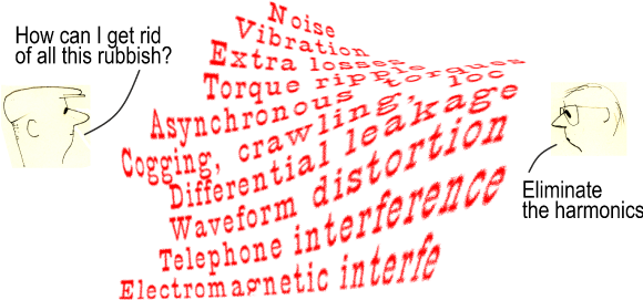
It is helpful to break the subject into a question of harmonics. Torque ripple is an unwanted harmonic of the shaft torque (which if perfectly smooth would have only an average value of harmonic order zero). It tends to cause speed ripple, which is an unwanted harmonic in the speed. In many cases the rotating inertia acts as a simple and adequate low-pass mechanical filter to attenuate the speed ripple. But in more complex systems the speed ripple may be dangerously amplified by torsional resonances which have particular harmonic orders. Resonance can lead to the amplification of torque harmonics, resulting in a pattern of cyclic torsional stress in the shaft and couplings which in turn may cause fatigue failure and/or the loosening of nuts and bolts. Torque ripple is often associated with vibration (and noise) which may be difficult to resolve by mechanical design alone.
If we cannot rely on the inertia to mitigate the effects of torque ripple, we must reduce the torque ripple at source. Now one of those hallowed engineering incantations every student mumbles outside the examination hall is that “torque equals flux times current”. It follows that we need to suppress the harmonics in both the flux and the current. But where are they, and how do they interact?
We can begin by saying quite simply that for AC machines the time-waveform of the current needs to be as close as possible to a pure sinewave.2 In inverter-fed machines this is the job of the current regulator and its PWM control algorithm. Inductance acts as a plain low-pass filter that helps to reduce unwanted harmonics (particularly at the carrier-frequency) in the current waveform, analogously to the mechanical filtering of the rotational inertia in relation to the speed.
But the concept of ‘flux harmonics’ is not quite so simple. We have to study the ‘flux times current’ product in terms of the interaction of the flux and current distributions inside the machine. In the classical theory these distributions resolve themselves into the flux-density distribution and the stator ampere-conductor distribution around the air-gap. We will use these easily-visualised concepts throughout this Diary (and in the related Videos 46-48). But we should make the observation that the harmonic composition of these distributions is not the immediate result of a finite-element analysis. This leads to the question of whether the torque should be analysed in terms of these harmonic distributions, or whether it should be calculated by Maxwell stress (which is the immediate result of a finite-element analysis). The harmonic distributions lead directly to the time-average torque (often with a finite-element analysis at only one rotor position), while the Maxwell stress gives the instantaneous torque at only one rotor position and must therefore be repeated over a complete cycle to get the average or running torque. Yet in spite of their obvious differences, the two approaches are more compatible than might at first appear, as we will see. (See also [3] and [4]).
For AC machines we use Fourier series to analyse the space-harmonics of the winding distribution, the flux distribution, and sometimes the permeance distribution within the machine, along the circumferential direction around the air-gap. (We also use Fourier series to analyse the time-harmonics in the current waveform, sometimes drawing on the theory of symmetrical components in cases of unbalanced operation; but in this Diary we will proceed with the assumption of balanced sinewave polyphase currents).
The torque is obtained from the integral (with respect to angle around the air-gap) of the product of two harmonic series : one representing the stator ampere-conductor distribution and the other representing some torque-producing attribute of the rotor, which we can call ‘the rotor flux’. (This might be the result of magnets or field windings or saliency, or some combination, and the term ‘rotor flux’ will be familiar especially to field-oriented control engineers who use it even with induction motors). The product of these waves is a wave of shear-stress at the rotor surface, whose integral over 360° is essentially the instantaneous torque. The central principle in the torque production is the remarkable result that a non-zero result for this integral (and therefore the torque) is produced only by the interaction of the working space-harmonics of the stator ampere-conductor distribution and the rotor flux, (sometimes called the ‘fundamental’ harmonics). All other space-harmonic interactions produce no net torque (provided that the current waveforms are balanced sinewaves). This remarkable fact follows directly from the principle of orthogonality in relation to the product of two Fourier series, and it represents the extraordinary filtering effect that occurs quite naturally in the configuration of AC machines.3
What it means is that for the purpose of calculating the average torque we can focus our attention on the working harmonics of the stator ampere-conductor distribution and the rotor flux, and ignore all other space harmonics.4 This is the basis of the dq-axis transformation (Park’s transform). The textbook development of Park’s transform starts out with the assumption of sinusoidal space-distributions of flux and ampere-conductors around the air-gap; and although it does not work with space-harmonics of either, it recognizes their existence by lumping their inductive effects into the ‘harmonic leakage inductance’ or ‘differential inductance’, while they contribute nothing to the torque.
The working harmonic space-distributions of the stator ampere-conductors and the rotor flux rotate in synchronism at the synchronous speed, and Park projects them on to a frame of reference rotating at synchronous speed. In this frame of reference (so-called dq axes) everything appears constant in steady-state operation. This being so, Park represents the distributed effects of the stator ampere-conductors and the rotor flux by the terminal quantities, current and flux-linkage. In order to provide a means of orientation (changing the relative spatial phase angle between the flux and the stator ampere-conductor distributions), Park needs two windings or coils, and he uses one aligned with the d-axis or field axis of the rotor, and the other one aligned with the q‐ or quadrature axis at right-angles to the d-axis. In this way he gets a flux-linkage ψd1 and current id1 for the d-axis winding and ψq1 and iq1 for the q-axis winding. The additional subscript 1 reflects the fact that the respective distributions are the working space-harmonics of the flux and the ampere-conductors.5
The average electromagnetic torque is now obtained from the equation

where p is the number of pole-pairs. In modern colloquial parlance, we can describe this as ‘insanely simple’ in view of the complexity of the physical system and its mathematical analysis. This is the E = mc2 of electric machine design. Its derivation often gets lost in analytical nuances, but the student’s mantra is clear : torque = flux × current!
We have to embellish it slightly. First, we need the flux times current for both axes of the dq model, not just one of them.6 Secondly, we need to distinguish flux-linkage (a terminal or circuit quantity) from flux (a distributed or field quantity). Thirdly, we need to add the coefficients 3/2 and p. We won’t go into the interpretation of these coefficients, or even discuss the units in the equation, but simply reflect on its ‘insane’ simplicity.
Can we use this elegant torque equation with finite-element analysis at a single rotor position, instead of a full-blown rotor-position-stepping total simulation with Maxwell stress? The answer is yes; and examples can be found in [3] and [4] and elsewhere. But of course it gives only the average or running torque, without any ripple, without any cogging, without any parasitic effects (such as stray losses and ‘harmonic leakage’ contributions to the terminal inductance). Like E = mc2, however, it’s quick.
Both the d‐ and the q-axis ‘coils’ representing the actual polyphase stator winding are ‘sine-distributed’ in the sense that their spatial (circumferential) ampere-conductor distributions are sinusoidal with only the working harmonic or fundamental number of pole-pairs p; but their inductances are supplemented by the aforementioned leakage inductance which includes ‘harmonic leakage’ associated with the other space-harmonics of the actual windings. This is necessary so that the dq-axis model can produce the correct terminal voltages (through the so-called Park’s equations). The inductance associated with the working space-harmonic of the dq-axis ampere-conductor distributions is called the ‘magnetizing inductance’ while the total inductance of the d-axis winding is the synchronous inductance Ld, and likewise Lq for the q-axis winding.
All these ideas are very old, and they have been used as the core of electric machine design for more than a century. It is 100 years since Park’s dq-axis transform was published and more than 130 years since Blondel published his two-reaction theory which also relies on the notion of sinusoidal distributions of ampere-conductors and flux. The modern expression of these principles is often in terms of space-vectors, the language of field-oriented control; while the actual elements (particularly flux-linkage, inductance, and torque) are computed by numerical analysis with vastly superior accuracy and insight to those available in the early days.
It is easy to forget that Park’s dq-axis transform relies on Fourier series analysis of the flux and ampere-conductor distributions, although it is glaringly obvious when it is applied to the inductance matrix in the derivation of Ld and Lq, [2,3]. But in mathematical terms, harmonic analysis by Fourier series is a linear operation. By ‘adding harmonics’ it embodies the principle of superposition and so its validity (or at least its accuracy) can be questioned when it is applied to a ‘nonlinear system’ such as an electrical machine. We might imagine that the ‘total simulation’ approach is not affected by this concern, and that would certainly be true of the torque calculation by Maxwell stress. It would also be perfectly valid to decompose a torque waveform into its harmonic components using Fourier series, after it had been calculated by Maxwell stress in a ‘total simulation’ that did not use the Park transform. But it is common, even in the ‘total simulation’ approach, to use Ld and Lq and Park’s circuit equations without stopping to consider whether the harmonic decomposition underlying the Park transform is completely valid. Even if the principle of superposition is acceptable in relation to the harmonic composition of the flux and ampere-conductor distributions, it remains the case that harmonics in these distributions introduce harmonic variations in Ld and Lq. In other words, they may vary with rotor position. It seems that we rarely acknowledge this possibility. Instead we sail through our machine design and our analysis with the tacit assumption that Ld and Lq are independent of rotor position, even though we readily accept their variation with current. It seems to work. Maybe that’s because of our mastery of winding layouts and our adherence to best practice! Nevertheless, there are engineers who do not trust the underlying assumptions completely, and so they resort to the ‘total simulation’ approach for everything — even the circuit analysis. The engineers of this school of thought might well be the first to describe the simplicity of the torque equation as ‘insane’, and they would have a point even though the term ‘insane’ is a bit extreme. Maybe they’re right. The ‘total simulation’ alternative is of course possible only with the most powerful simulation software; it certainly was not possible a generation ago. A complete analysis of these interrelated issues would be a hard and complex task for a PhD student; and frankly I don’t know if it has been tackled, or to what extent. The full gamut of questions and theoretical implications would seem to be outside the normal scope of our busy daily work in machine design. Let’s hope so!
1 As an example of a machine that produces constant torque, the Faraday disk can be cited, as well as certain types of homopolar superconducting machine, [1].
2 This excludes the brushless DC motor which operates (ideally) with ‘squarewave’ current waveforms [2]. It also excludes the DC commutator motor and the switched reluctance motor, since these are not AC machines.
3 Cogging torque is excluded from this discussion, as it is a separate effect that arises even with zero current.
4 The other space-harmonics are still important in the calculation of stray losses, total winding inductance, and terminal voltage.
5 Many of these ideas were derived from the work of Blondel 30 years earlier. In their original publications on the dq-axis theory in the 1920s, Park, Doherty, Nickle and others generously acknowledged Blondel.
6 This is true even in the DC commutator motor which is probably the original source of the ‘flux times current’ notion. In the DC motor, only the d-axis flux-linkage is normally considered to be active in producing torque, although both terms in eqn. (1) are in fact present.
Further reading
see also Engineer’s Diary No. 67
[1] A.D. Appleton, Motors, Generators, and Flux Pumps, Cryogenics, June 1969, pp. 147-157.
[2] J.R. Hendershot & T.J.E. Miller, Design of Brushless Permanent-Magnet Machines, Motor Design Books LLC, 2010, sales@motordesignbooks.com ISBN 978-0-9840687-0-8
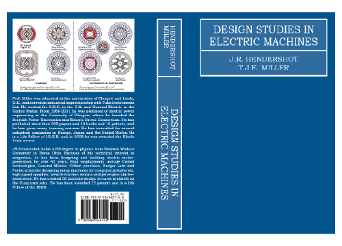
[3] J.R. Hendershot & T.J.E. Miller, Design Studies in Electric Machines, Motor Design Books LLC, 2022, sales@motordesignbooks.com ISBN 978-0-9840687-4-6
[4] Nicola Bianchi, Electrical Machine Analysis Using Finite Elements, Taylor & Francis, 2005, ISBN 0-8493-3399-7

