 Fig. 1 Eddy-currents in a permanent magnet
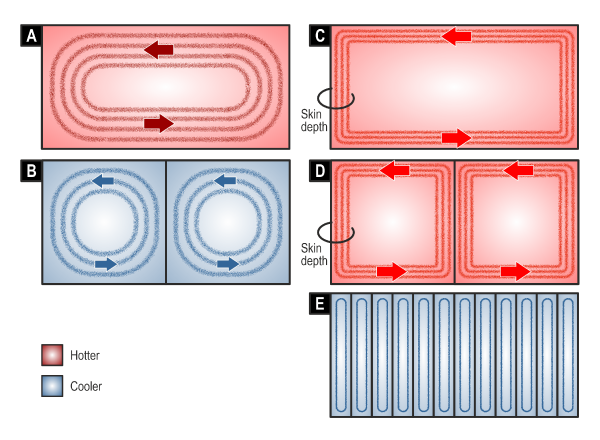
Imagine a block of permanent magnet material in an IPM, Fig. 1. Our line of sight is parallel to the direction of magnetization, at right angles to the plane of the diagram. We are looking through the rotor steel and straight into the magnet. We see eddy-currents swirling round in a pattern that extends through the entire volume of the magnet. Whatever the cause of these eddy-currents, they generate Joule loss (I2R loss). The current-density J varies throughout the volume, so really the Joule loss is the integral of J2ρ over the volume, where ρ is the resistivity.
Fig. 1A tries to show some of the properties of eddy-currents in the resistance-limited condition [1‐3]. They flow in closed loops, and each loop can be considered to link a certain fraction of the alternating flux that penetrates the magnet. This flux can be considered as a deviation or perturbation of the steady-state flux which is the resultant of the magnetization of the magnet and the d-axis component of the armature current (both of which are constant in the steady state). Larger loops towards the outside of the pattern link more flux and therefore experience a greater induced EMF (by Faraday’s law), but the currents in the outer loops also have a longer path and therefore a larger resistance. Overall, the field equations find a solution with a certain distribution of current-density not unlike that in Fig. 1. This solution applies at only one frequency, which we can take to be a harmonic in the flux perturbation. At this stage we don’t need to know the cause of this perturbation; for now, we only need to accept that it exists. In the resistance-limited condition, the eddy-currents lag behind the alternating flux by 90° at the harmonic frequency, and although they produce a “reaction” field, it is negligible, so there is no material change in the overall flux. The main effect of these eddy-currents is the heat generated by the Joule loss. Because the exciting frequency may be quite high (up to several kHz) and the resistivity of the magnet also quite high (some 80 times the resistivity of copper), the loss density may very well be problematic — enough in some cases to raise the magnet temperature to the point where there is some irreversible loss of magnetization. So resistance-limited eddy-currents may appear to be calm and well-ordered, but they are not necessarily benign.
Segmentation of resistance-limited eddy-currents
One of the ways to reduce the eddy-current loss is to suppress the eddy-currents by segmentation of the magnets, Fig. 1B, [4]. The magnet has been split into two equal segments, insulated from each other, [5]. This reduces the eddy-currents because the flux-linkage of the smaller loops is reduced by about half, while the resistance is reduced by not quite so much. We can persuade ourselves of this logic if we consider the loss to go with φ 2/R, where φ is some characteristic measure of flux and R is some characteristic measure of resistance. The notion that the loss is of the form φ 2/R is a characteristic property of resistance-limited eddy-currents: indeed, it is almost a definition of the resistance-limited condition.
While Fig. 1B shows the principle of segmentation, as a first step, in general a larger number of segments is needed to reduce the eddy-current losses to an acceptable level, [4]. The question is how much segmentation is required to reduce the magnet loss to an acceptable level? The answer depends on the particular machine: its geometry, its windings, and its operating conditions; and to some extent on the characteristics of the inverter. Calculation is necessary.
Inductance-limited eddy-currents (no segmentation)
Before we rush into calculation, however, we need to learn more about the innate behaviour of eddy-currents. Imagine that the frequency of the alternating flux perturbation is raised to a much higher level. The resistance-limited eddy-currents that were swirling placidly and quietly around in Fig. 1A now change their character. They become angry. They fly out to the extreme edges of the conducting block of magnet, where the current-density may reach very high values, Fig. 1C. The total amount of the eddy-current becomes much larger, and the eddy-currents produce a reaction field that tends to annul the applied exciting field. In effect, the eddy-currents try to expel the excitation flux from the body of the magnet. This is a manifestation of Lenz’ law. In this condition they behave rather like the short-circuit current in the secondary of a transformer, and they are 180° out of phase with the exciting flux. They are limited in magnitude by the flux-exclusion mechanism: in other words, if the frequency is high enough, we will get just enough eddy-current to annul the exciting field in the body of the magnet, and no more. Eddy-currents in this condition are called inductance-limited.1 Note that the path resistance is high because the eddy-currents are confined to a narrow zone which we characterize as the skin depth, Fig. 1. (See also [1,2]).
Think of inductance-limited eddy-currents as angry eddy-currents, and think of resistance-limited eddy-currents as calm and orderly (even though they may be generating too much heat).
Inductance-limited eddy-currents with inadequate segmentation
We might expect to be able to reduce the inductance-limited eddy-currents by segmentation, as we did with the resistance-limited eddy-currents in Figs. 1A & B. In Fig. 1D the block is divided into two segments, but the eddy-currents are still angry. Whatever is driving them is still sufficient to fling them to the outer edges of the segments. Whatever resistance is impeding them is not enough to calm them down. They remain limited by inductance, or by the inductive flux-exclusion principle. The total current paths are now longer, so the total loss may well have increased.
We have reached this disturbing conclusion by a hand-waving argument with an “anthropomorphic” description of the eddy-currents — “angry”, “calm and orderly”, etc. Is there any possible truth to it? For a well-documented, clear explanation see the papers by Prof. Yamazaki & Co. [4‐6]. We will return to some of Prof. Yamazaki’s observations later.
How can we reduce the eddy-current loss in the case of inductance-limited eddy-currents? Can we make them calm down by increasing the resistivity? It is true that increasing the resistivity raises the frequency at which the eddy-currents can be said to be inductance-limited. But as long as they are in the inductance-limited condition, the answer is “no”. Those angry eddy-currents are going to flow, come what may, in the process of annulling the alternating component of flux in the magnet body. If we put more resistance in their path, they will simply generate more Joule loss. In simple language, I isn’t going to change, so if we increase R the loss will go up. To suppress the angry eddy-currents by resistivity, we might have to increase the resistivity by a large amount. In practice this might be achieved by switching to ferrite magnets, but otherwise we need to have more segments — a lot more segments. We almost need to “laminate” the magnets. This is shown in Fig. 1E.
Fine segmentation is needed to quell inductance-limited eddy-currents
Prof. Yamazaki [4‐6] gives a rule-of-thumb for the size of segment needed to quell the angry eddy-currents: the shortest dimension should be less than twice the classical skin-depth. Yamazaki published an impressive study using 3D finite-element analysis, with classical analysis of the eddy-current behaviour, backed up with physical experiments; the references are well worth studying, including the much older analyses in [1 & 2].
We might ask ourselves, “When might the eddy-currents be angry?” or “What did I do to make them angry?” This is a question of design parameters, but let’s start by enumerating the three main causes, [10]:
- Asynchronous ampere-conductor waves produced by the space-harmonics in the stator winding distribution. (These proliferate when there are time-harmonics in the current waveform).
- Permeance harmonics attributable to slotting.
- PWM carrier harmonics: that is, high-frequency harmonics in the voltage applied at the machine terminals by the PWM inverter.
In the IPM, all three of these produce similar harmonic fluctuations in the magnet flux in the region of the magnet itself. But they differ widely in magnitude and frequency, and in the resulting eddy-current loss components. It is dangerous to make general statements, but in the literature we find several examples where the PWM harmonics are the most likely cause of angry inductance-limited eddy-currents. This is logical because their frequencies may be of the order of 10 or more times higher than the frequencies of the other components.
On the other hand it is noticeable that a large number of published papers completely ignore the carrier harmonics (especially those that deal with surface-magnet motors), and many of them assume ab initio that the eddy-currents are resistance-limited. (Prof. Yamazaki [4] points out that in the IPM the eddy-currents have a greater tendency to become inductance-limited because the iron surrounding the magnets enhances their reaction field). Unfortunately the machine designer may not have much information about the PWM carrier harmonics of the inverter, especially in the early stages of a design. In such cases it may be helpful to work with a simple standard PWM algorithm such as the sine/triangle algorithm, [7].
An interesting study of scale effects was published by Bianchi [8], mainly in connection with surface-magnet machines but still relevant to the IPM. He showed that eddy-current losses tend to increase very rapidly with the size of the machine.
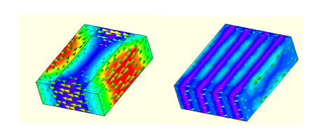 Fig. 2 Eddy-currents in unsegmented and segmented magnet
The calculation of eddy-current losses is squarely in the domain of finite-element analysis, as we can see in Fig. 2. But the understanding of the sources of excitation is very much in the realm of the classical theory of electric machines and inverters, as is obvious from the causes listed earlier. 2 Combining these two aspects of the problem may be quite a complex undertaking, and in a forthcoming video we will examine ways in which they may be treated separately. In the finite-element analysis of eddy-current losses, we will certainly see images like those in Fig. 2, and we’ll be thinking about the angry eddy-currents and how to quell them by the appropriate degree of segmentation — not too much, and not too little !
Special note — While the general properties of eddy-currents have been understood for a long time [1‐3], the unravelling of the complex eddy-current problem in electrical machines owes a great deal to the work of Prof. Yamazaki and his colleagues in the early 2000s. Only three references are included here, but there are several others worth studying, including some that cover surface-magnet machines and core losses as well. Yamazaki also discussed the need for insulation between magnet segments.
1 The term inductance-limited can be thought of as borrowed from the theory of coupled circuits (Videos 43 & 44), in which the limiting inductance is the leakage inductance. For this reason the dynamic inductance at the terminals of the circuit that is producing the exciting flux is reduced. (In the complexity of a machine this aspect applies to the harmonic components of the total armature inductance).
2 In [9], Bianchi & Fornasiero published an “index” of rotor losses which tries to rank different machine configurations according to their susceptibility to eddy-current effects.
Further reading
[1] P. Hammond, The calculation of the magnetic field of rotating machines. Part 3. Eddy currents induced in a solid slab by a circular current loop. Proc. I.E.E., Vol. 109C, 1962, p. 508
[2] R. L. Stoll & P. Hammond, Calculation of the magnetic field of rotating machines. Part 4. Approximate determination of the field and the losses associated with eddy currents in conducting surfaces. Proc. I.E.E., Vol. 112, No. 11, November 1965, pp. 2083‐2093
[3] R.L. Russell & K.H. Norsworthy, Eddy currents and wall losses in screened-rotor induction motors, Proc. I.E.E., Vol. 105A, 1958, pp. 163-175
[4] K. Yamazaki et al, Effect of Eddy Current Loss Reduction by Segmentation of Magnets in Synchronous Motors: Difference Between Interior and Surface Types, I.E.E.E. Transactions on Magnetics, Vol. 45, No. 10, October 2009, pp. 4756‐4759
[5] K. Yamazaki et al, Investigation of Eddy Current Loss in Divided Nd-Fe-B Sintered Magnetsfor Synchronous Motors Due to Insulation Resistance and Frequency, I.E.E.E. Transactions on Magnetics, Vol. 44, No. 11, November 2008, pp. 4269‐4272
[6] K. Yamazaki and A. Abe, Loss Investigation of Interior Permanent-Magnet Motors Considering Carrier Harmonics and Magnet Eddy Currents, I.E.E.E. Transactions on Industry Applications, Vol. 45, No. 2, March/April 2009, pp. 659‐665
[7] T.M. Rowan and R.J. Kerkman, A New Synchronous Current Regulator and an Analysis of Current Regulated PWM Inverters, I.E.E.E. Transactions on Industry Applications, Vol. IA-22, No. 4, 1986, pp. 678‐690
[8] N. Bianchi et al, Relationship Between Rotor Losses and Size of Permanent-Magnet Machines, I.E.E.E. Transactions on Industry Applications, Vol. 49, No. 5, September/October 2013, pp. 2015‐2022
[9] N. Bianchi & E. Fornasiero, Index of rotor losses in three-phase fractional-slot permanent-magnet machines, IET Electr. Power Appl., Vol. 3, Iss. 5, 2009, pp. 381‐388
[10] J.R. Hendershot and T.J.E. Miller, Design of Brushless Permanent-Magnet Machines, sales@motordesignbooks.com, 2010

