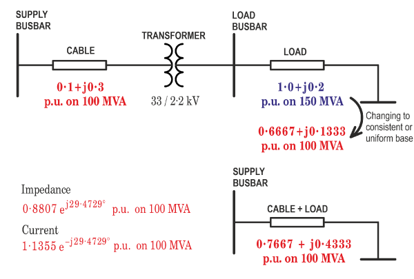
 Fig. 1 An example of a quick power-system calculation in p.u.
The first time I saw the expression “p.u.” was in an examination paper on electric power-systems, when I was a student-apprentice. Fortunately it was the previous year’s paper, not the one I would face a few months later. The expression “p.u.” caught my eye. Up to that point I had become familiar with volts and amps; but the idea that voltages and currents could be measured in a common unit had not occurred to me. Nor would it have been a comfortable idea, half a century ago. Why would such an idea occur to anyone? 1
1. Definition — Normalization, base quantity, relative values
Per‑unit quantities are quantities that have been normalized to a base or reference value. For example, consider a motor with a rated power of 5 kW. “Rated” means the normal level when the motor is “fully loaded”. “Full load” power can be defined in different ways, but whatever its definition we can take it as the “base” power, that is, 1.0 per-unit or 100%. If a 5-kW motor is operating at only 3 kW, the per‑unit power is 3/5 = 0.6 p.u. (or 60%).
Imagine two motors, one of 5 kW rating, the other of 50 kW rating. They are connected in parallel to a supply that is rated at 150 A. Suppose that the smaller motor draws its rated current of 7.5 A , while the larger one draws 75 A. If we choose 150 A as the base current, then the first motor is drawing 7.5/150 = 0.05 p.u. while the second one draws 75/150 = 0.5 p.u., relative to the 150 A base. The total current is 0.55 p.u., or 82.5 A. Though trivial, this example clearly expresses the fact that the smaller motor is taking 5% of the rated supply current while the larger one is taking 50%. The per-unit values help us to focus on the capacity of the supply and the extent to which it is loaded. Evidently in this case we could add motors and almost double the load.
In general, 2

where x is a per‑unit value, X is an actual value, and Xb is the base value. X and Xb are expressed in ordinary units, such as volts, amps, watts, ohms, etc.; but x has no units: it is dimensionless.
Per‑unit quantities express relative values—that is, relative to the base value. The choice of base value is important. In the simple example quoted above, with only one motor to be considered, a natural choice of base was the rated value. But in a more complex system with more than one component, the choice of a single base value requires a little more consideration. It should also be obvious that all base values should be consistent or uniform throughout the whole system, (with a slight modification for systems containing transformers; see below). The base values should always be stated when a per-unit system is being used.

I once heard a design engineer say “I never use per-unit values; they cause confusion and they are a complete waste of time”. Let’s call him “Cap-Man”. Cap-Man used to design high-voltage power capacitors to be installed on long-distance transmission systems. His focus was on his capacitors, not on the complete system. He cared passionately about the actual volts and amps in his capacitors, but he had no need to consider the size of his capacitors relative to the overall transmission system. Those considerations were the preserve of the power-system analysts and planning engineers, the “systems people” as distinct from the “components people”. It must be admitted that his opinion and his habits were entirely understandable and reasonable, relative to the scope of his daily work, even though his words may have been a little on the dogmatic side. If Cap-Man were to be told that JMAG could work in many different units, but not in per-unit, he would not be disappointed in the slightest. So who needs per-unit systems?
Networks with many different levels of voltage and current
Per‑unit systems are especially useful when we have a more complicated network with transformers, generators, transmission lines, cables, capacitors, reactors, motors, switchgear, etc., in which there may be several different voltage and current levels. A simple example is shown in Fig. 1, and analysed in detail in Video 50. One group of engineers who use per-unit systems is the community of power-systems engineers, especially those concerned with the design and operation of the system as a whole.
But there are other valuable attributes of per-unit systems that may apply to single components as well as to complete systems.
Narrow range of values representing normal operation
When quantities are expressed in per‑unit, most numerical values are in the range 0‐1 under normal operation; higher values occur under overload or transient conditions. This helps in scanning the results of a load‑flow analysis or fault study — or indeed any performance data — because abnormal conditions are immediately recognizable: for example, currents outside the 0‐1 range, or voltages that deviate more than a few percent from 1.0 p.u.
Elimination of arbitrary or peculiar coefficients
Engineering formulas often contain “funny” coefficients such as 2π/√2, or constants such as 1.358. Often these are conversion factors for units, but they may stem from conventions or assumptions laid out in the development of the theoretical model. Sometimes their origin is obscure. In a well-chosen per‑unit system such factors are common to both the actual and the base values, so they vanish. Per‑unit expressions are therefore less cluttered, and they express the essential physical nature of the system economically.
An example is the normalization of power in a three‑phase system. The equation is written first in ordinary units; then the same equation is written for the base quantities, also in ordinary units. The first equation (i) is then divided by the second (ii), to give the normalized or per-unit equation, (iii). Note that all the quantities (voltage, current, and power) are normalized at the same time. It is therefore necessary to choose the base values for all of these quantities at the same time. The √3 factor disappears, because it is peculiar to the equations in ordinary units, and it has no significance in terms of the normalized equation or units. On the other hand, the power-factor cos φ remains, because it is part of the essential physical nature of the system operation, regardless of the units. For this to happen, it is sufficient to choose the base power-factor (cos φ)b as 1. That is a reasonable choice, because the power-factor in the per-unit equation is then relative to a sensible maximum value.

The per-unit equation is simpler, being unencumbered with arbitrary factors that apply only to particular configurations and particular choices of quantities, for example, line-to-line quantities. If we were to use line-to-neutral quantities the √3 coefficient would be replaced by 3 in the first two equations in ordinary units; but the per-unit equation would be unchanged. We can expect per-unit equations to remain unchanged whether the load is connected in wye or delta, or even if the number of phases changes.
Reduction to Essentials
The normalised power equation in eqn. (2) can be said to be an example of “reduction to essentials”. Another example is the torque equation in Engineer’s Diary No. 68, which in normalized form is

. . . without 3/2, without the number of phases m, and without the number of pole-pairs p. The per-unit equation can be said to capture the essential behaviour of the machine, without any extraneous or non-essential parameters or coefficients. After calculations are completed in per-unit, the ordinary values can be recovered very simply from the defining equations for the base quantities.
While this argument may be aesthetically appealing, it is easy to see why Cap-Man might be fuming and spluttering at the suggestion that p and m and the 3/2 coefficient might be “extraneous” or “non-essential”. To him, these arguments might seem academic, sophist, and even obscure.
Use of the per-unit system to rationalise a system of equations
It is not much discussed nowadays, but at least one formulation of the dq-axis transformation leads to non-reciprocal mutual inductances between the armature (stator) and the field (rotor) circuits in the classical synchronous machine. This issue is discussed (and resolved) in the great classical work by Concordia [2], and again in [1]. By choosing different bases for the stator and rotor currents, the symmetry of the inductance matrix is magically restored, and the repugnant non-reciprocal mutuals are swept away. The process is rigorous but slightly untidy, and it is discussed in more detail in Engineer’s Diary No. 72 and Video 51.
Standard formulas for three‑phase systems
For three-phase systems there is a set of standard formulas for manipulating per-unit values, using the line-line kV and the MVA to define the base impedance in any section of the system. A detailed example is worked out in Video 50, but one or two important points are given here.
The example is shown in Fig. 1. The transformer divides the system into two sections operating at different voltages. On the HV (high-voltage) side the cable impedance is quoted in p.u. on a base of 100 MVA. On the LV (low-voltage) side the load impedance is quoted in p.u. on a base of 150 MVA.
There are two key points to note.
| (i) | The per-unit impedances must be referred to the same base. Therefore the load impedance is transformed to the HV base, using the ratio of base MVAs. |
| (ii) | The transformer is simply removed, using the principle that if the bases are consistent the transformer has no effect on the per-unit impedances. |
It then becomes possible to add the two per-unit impedances for the cable and the load, producing the simplified system diagram in the lower half of Fig. 1. Using this, we get the total system impedance immediately, and the current. In Fig. 1, both of these are given in p.u. on the HV base (100 MVA, 33 kV). The values in ordinary units can easily be recovered (see Video 50).
In Video 50 the same calculation is repeated entirely in ordinary units, to show the effectiveness of the p.u. calculation particularly in removing the transformer. The simplifications may not seem great in this simple example, but they certainly help in more complex systems. For example, in the schematic diagram of a complex transmission system the impedances of all elements can be displayed with per-unit values on the same base, reflecting their relative influence on the operation of the whole system. It means that we don’t have to keep re-calibrating our “mental voltmeter” every time we focus on a different element in the system. We can think of this as a “level playing-field”. In ordinary units the impedances would appear with widely different values, making it more difficult to assess the relative influence of different elements; moreover, the transformers would have to be retained in the schematic diagram complete with their voltage ratios, adding to the complexity.
Finally a word of caution. It is easy to fall into the trap of thinking that per-unit notation embodies the scaling laws of electric machinery; but this is not the case. There is in fact no unique set of scaling laws, just as there is no unique per-unit system. In scaling the size of an electric machine, even while keeping all its geometric proportions the same, we sometimes find that a parameter in ordinary units does not scale at the same rate as the same parameter in per-unit. Perhaps we should look at this in a future Diary or video.
1 Fig. 1 contains the expression “p.u.” in much the same kind of context as in that ancient examination paper. If you haven’t seen it before, try to imagine its effect on an unwitting undergraduate student! Some early systems of units did have the appearance of using common units for different quantities — notably electromagnetic units or EMU. But these units were not dimensionless and not normalized (referred to a base quantity).
2 Boldface lowercase letters are used for per-unit quantities.
References
[1] Harris M.R., Stephenson J.M. and Lawrenson P.J., Per‑Unit Systems, Cambridge University Press., 1970.
[2] Concordia C., Synchronous Machines, John Wiley & Son, 1951.

