Contents
1. Introduction
2. Efficiency map creation method
2.1 Direct FEA method
2.2 Look up table (LUT) method
2.3 ROM method
3. Efficiency map comparison
4. Summary
5. References
1. Introduction
The efficiency map is an indispensable tool for motor development and FEA has become widely used to create them instead of using measurements. This is due to the FEA approach being less time consuming and available during the design phase. However, as efficiency of motors is becoming high, greater accuracy is required for the efficiency map since a significant part of the design work is devoted to improving efficiency. The conventional method takes several simplifications to reduce the creation time which cause accuracy issues. However, when created without those simplification, it provides results accurate enough for evaluating high efficiency designs. In this report, three methods are compared on a PMSM showing that the accurate version is necessary for advanced applications such as EV. It shows that the accurate version based on FEA without any simplification is necessary for creating efficiency maps with high accuracy.
2. Efficiency map creation method
2.1 Direct FEA method
This method reproduces the same procedure of a measured efficiency map. The procedure consists of two steps which are; first to find the maximum torque for each speed point and secondly to find a current vector which provides minimum loss as shown in Table.1. The FEA used here is conducted as a coupled simulation with a control simulation model so that the current vector control is accurately reproduced in the simulation. Note that all losses are automatically taken into account in the FEA as described.
2.2 Look up table (LUT) method
In this method, lookup tables, which output voltage, loss and torque as a function of the current vector and speed, are generated using FEA with sinusoidal currents. Using those lookup tables, the efficiency map is created as shown in Table.1.
To estimate the current vector for the MPME, the lookup tables are used allowing to skip a large number of FEA calculations.
The loss is a summation of the copper loss, iron loss, AC loss and magnet loss, each of which is calculated as follows. An approximation of the PWM loss is included via a correction factor. The AC loss is calculated as eddy current loss in the winding conductors induced by flux passing through the slot opening ignoring the flux from the gap and leakage flux in the slot. For the magnet loss calculation, the eddy current loss is calculated as a function of the inflow flux to the magnet.
2.3 ROM method
The direct method explained above would require an enormous number of FEA calculations. To reduce the FEA calculation steps and the time cost, the FEA model can be replaced with a Reduced Order Model (ROM) as shown in Table.1. The ROM is based on a set of voltage equations with lookup tables made from FEA. Those ROM have been used in Model-In-the-Loop (MIL) simulation as well as Hardware-In-the-Loop (HIL) simulation where highly accurate models is required for ECU design and tests.
Table 1. Three methods of efficiency map creation
| Direct method | LUT method | ROM method | |
| Current vector estimation | Estimated by parametric FEA study coupling the control varying the current vector as same as the measurement | Estimated from the LUT obtained by FEA with the sinusoidal current | Estimated by parametric study using the ROM varying the current vector as same as the measurement |
| PWM iron loss | Calculated in FEA | Correction | Calculated in FEA |
| AC loss | Calculated in FEA | Correction | Calculated in FEA |
| Magnet loss | Calculated in FEA | Correction | Calculated in FEA |
3. Efficiency map comparison
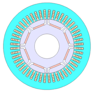
Performances of the LUT method and the direct method are compared on a permanent magnet synchronous motor whose specifications are shown in Fig. 1 and Table 2. The control strategy is the maximum power/maximum efficiency control.

Fig. 1 Motor geometry
Table 2 Motor Specification
| Output power | 80 (kW) |
| Poles | 8 |
| Slots | 48 |
| Outer diameter | 212 (mm) |
| Stack length | 200 (mm) |
| Inverter voltage | 600 (V) |
| Inverter max. current | 250 (A) |
| Carrier frequency | 6 (kHz) |
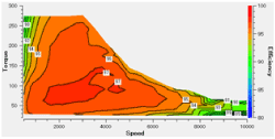
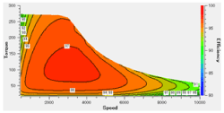
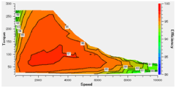
Resulting efficiency maps and their difference are shown in Fig. 2 and Fig. 3. The difference between the ROM method and the direct method is relatively small comparing to the one between the LUT method and the direct method. Those arises in the regions with medium speed and high torque, and high speeds.
 (a) Direct method
 (b) LUT method
 (c) ROM method
Fig. 2 Efficiency maps
You need to sign in as a Regular JMAG Software User (paid user) or JMAG WEB MEMBER (free membership).
By registering as a JMAG WEB MEMBER, you can browse technical materials and other member-only contents for free.
If you are not registered, click the “Create an Account” button.
Create an Account Sign in


