Contents
1. Introduction
2. Motor specifications and system configuration
2.1 Motor and resolver
2.2 Motor
2.3 Resolver
2.4 System configuration
3. Analysis models
3.1 Mesh models
3.2 Resolver model resolution
3.3 Control system model
3.4 Resolver model
4. Motor torque ripple control verification
4.1 Torque ripple control verification at resolver eccentricity (Function verification: Scenario 1 to Scenario 4)
4.2 Torque ripple control verification when accounting for the effect of flux leakage from the motor (Performance verification: Scenario 5 and Scenario 6)
5. Considerations
6. References
1. Introduction
VR-type resolvers are widely used as angle sensors to control the rotation of traction motors for electric vehicles and hybrid vehicles. As increasingly high efficiency, low vibration, and low noise are required, it is necessary to run detailed current vector control for motors while receiving angle signals from the resolver. Conversely, in order to realize saving space for the traction motor, the resolver is positioned closer to the motor. The flux leakage from the motor which is made to be of a high output density therefore disturbs the resolver angle detection. In addition, due to errors in assembling the resolver, there are further increases in angle detection error should any axis shifts occur.
Motor torque ripple control is verified by modeling the motor and the resolver with JMAG-RT assuming a motor drive system for driving. Function verification and performance verification is run on several items, such as the degree of resolver eccentricity, and accounting for the effect of flux leakage that occurs as a result of the position where the resolver is installed. The results of these verifications are then shown. The number of mesh divisions for the resolver that is required to run the verifications is also shown during the verification process, and it is reported confirmed that JMAG-RT models can be used for verification objectives much like those featured in this document.
2. Motor specifications and system configuration
This shows the specifications of the motor and resolver for which torque ripple control verification is run.
2.1 Motor and resolver
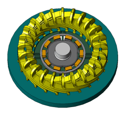
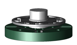
The motor and resolver installed on the same axis are shown in Fig. 1. As can be understood from the right side of Fig. 1, the distance between the resolver and the motor rotor part is considerably close (5.25 mm in these circumstances).


Fig. 1 Motor and resolver (Left: Whole, Right: Motor rotor part and resolver core)
2.2 Motor
The motor used for torque ripple control verification is an interior permanent magnet synchronous motor, with the shape shown in Fig. 2. Some of the motor specifications are shown in Table 1.
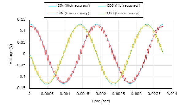
 Fig. 7 Output coil voltage waveforms
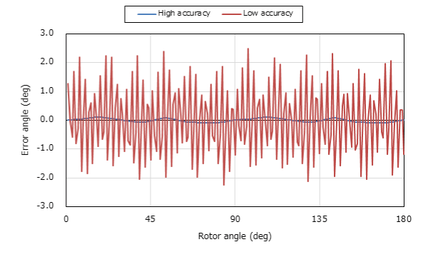
 Fig. 8 Resolver angle detection error
You need to sign in as a Regular JMAG Software User (paid user) or JMAG WEB MEMBER (free membership).
By registering as a JMAG WEB MEMBER, you can browse technical materials and other member-only contents for free.
If you are not registered, click the “Create an Account” button.
Create an Account Sign in


