Contents
1. Introduction
2. AC loss modeling
3. Control calibration Example: Current Vector Calibration for Maximum Efficiency Control
3.1 Motor and Control Specifications
3.2 Plant model specifications
3.3 Calibration method of the current command value
3.4 Calibration result
4. Summary
5. References
1. Introduction
Control parameter calibrations on Model-In-the-Loop Simulation (MILS) with Finite Element Analysis (FEA) based motor models is expected to be a standard procedure in the Model-Based-Design (MBD) for motor drive system developments. Although current standard motor models of electric machines can be used to see its basic behavior, the accuracy is not enough for the control parameter calibrations, especially for the estimations where AC loss in solid conductor windings is not ignorable. In this paper, the motor plant model considering AC loss is presented and applied for the control calibration of a PMSM maximum efficiency control.
2. AC loss modeling
A PMSM with solid conductor windings is focused herein. A voltage equation for a phase of a PMSM is written as (1) where \(V_i, \ R_i, \ I_i \ and \ \phi_i\) are voltage, resistance, current and flux linkage of phase i, respectively. The iron loss can be included by adding an equivalent resistance in parallel with the second term on the right hand side of (1).
In order to take account of the AC loss, \(R_i\) is replaced with the Cauer circuit which can represent reactions by eddy currents in a conductor. The inductance and resistances in the Cauer circuit are calculated by the analytical method.
\(V_i = R_iI_i + \frac{d\phi_i}{dI_i}\) (1)
3. Control calibration Example: Current Vector Calibration for Maximum Efficiency Control
3.1 Motor and Control Specifications
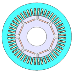
Fig. 1 and Table 1 show the cross-section and specifications of the motor. Fig. 2 shows the control model. The current vector is controlled by the PI control. The current vector, which is the command value, is selected so that efficiency is maximized at each operating point by calibration.

Fig. 1 Cross-section of the motor
Table 1 Motor specifications
| Objective functions | 8/48 |
| Core material | 35JA300 |
| Magnet | NdFeB, Br=1.2 (T) |
| Output | 80 (kW) |
| DC Voltage | 600 (V) |
| Maximum current | 250 (A) |
| Carrier frequency | 6 (kHz) |
You need to sign in as a Regular JMAG Software User (paid user) or JMAG WEB MEMBER (free membership).
By registering as a JMAG WEB MEMBER, you can browse technical materials and other member-only contents for free.
If you are not registered, click the “Create an Account” button.
Create an Account Sign in


