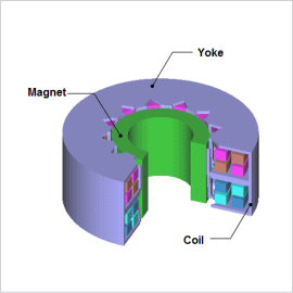
Overview

To measure them, begin to gradually reduce the load on the stepper motor from a stationary state, measure the pull-in torque when it begins to rotate, begin to gradually increase the load in sync with the pulses from a rotating state, and measure the pull-out torque when it loses synchronism. It is necessary to carry out transient analysis while changing the load in order to solve this phenomenon in magnetic field analysis. While it is possible to calculate it using an equation of motion with JMAG’s 3D transient response analysis, such calculations take too much time. With JMAG, it is possible to create a motor model that is detailed and conforms to a real machine, and that accounts for spatial harmonics and magnetic saturation characteristics that are included in a stepper motor. By importing this motor model, a “JMAG-RT model,” to the control/circuit simulator, it is possible to derive the stepper motor’s pull-in and pull-out torques quickly and accurately because it accounts for the motor’s magnetic saturation characteristics and spatial harmonics.
This note presents how JMAG-RT can be used to calculate holding torque and coil inductance that varies with current. The result is the JMAG-RT motor model used as a reference for a circuit / control simulator that runs a transient analysis to obtain pull-in and pull-out torques of the stepper motor. By also using a single JMAG-RT motor model and changing the circuit on the circuit/control simulator, it is possible to obtain the characteristics of two types of drives: a bifilar winding with a unipolar drive, and a monofilament winding with a bipolar drive. Other parameters are the same for both analyses.
Pull-In and Pull-Out Torques characteristics
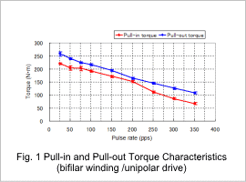
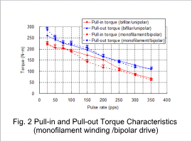
The pull-in and pull-out torque characteristics are shown in fig. 1 and fig 2. Fig. 1 shows the result with bifilar winding and unipolar drive. Fig. 2 shows the result with monofilament winding and bipolar drive along with the result of fig. 1. The I-shape in each figure represents approximate error range of pull-in and pull-out torques at each point. Error range is shown in both figures.
The self starting region and slew region can be determined from fig. 1. These results indicate the correlation between the torque and pulse rate required for the motor to run on without losing synchronized stepping.
As shown in fig. 2, the result of bifilar winding with unipolar drive and the result of the monofilament winding with bipolar drive have similar pull-in and pull-out torques when other parameters are the same.


