Overview

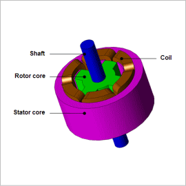
With JMAG, it is possible to create a detailed model that conforms to a real machine and accounts for the torque’s dependency on rotor angle and the magnetic saturation characteristics of the magnetic circuit in an SR motor. Importing this motor model, a “JMAG-RT model,” to a control/circuit simulator makes it possible to carry out a linked simulation that accounts for an SR motor’s detailed characteristics as well as a motor drive’s control characteristics. This kind of operation makes control simulation to suppress an SR motor’s torque pulsation possible.
In this Application Note, after using JMAG-RT to obtain an SR motor’s torque and inductance characteristics, the JMAG-RT model is imported into a circuit/control simulator, voltage is applied to drive the SR motor, and the torque pulsation is analyzed. By evaluating the obtained torque pulsation in detail, investigations can be carried out to reduce the torque pulsation (this Application Note does not incorporate actual attempts to reduce torque pulsation).
Rotation Speed Waveform / Torque Waveform / Current Waveform
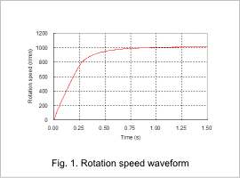
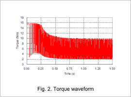
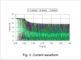
Fig. 1 shows the rotation speed waveform, fig. 2 shows the torque waveform, and fig. 3 shows the current waveform when the SR motor is driven.
A large phase current flows immediately after starting because the rotation speed is slow and the starting voltage is small, but this is suppressed to an upper limit by the current limit value. At this time, a lot of torque is generated, and the rotation speed increases rapidly.
Once the rotation speed increases a certain amount, the rotation speed, torque, and current settle into a steady state because the starting voltage rises and the current limit becomes irrelevant. The steady state torque oscillates. Evaluation of excitation timing and control of the current waveform itself are possibilities for ways to reduce this.


