*Please prepare a license ID and password for the license administrator.
*It is different from the service for JMAG WEB MEMBER (free membership). Please be careful.
Overview

The demand for low fuel consumption of automobiles has been increasing every year, and types of auxiliary systems and devices such as power steering and cooling pumps are being electrified to support this. For this reason, the amount of electricity used has increased every year for general gasoline-powered vehicles, and the demand for higher output power for alternators which supply electricity is increasing. However, since it is not allowable to increase the vehicle size to increase the generating capacity, it is necessary to increase the power density. Furthermore, it is necessary to achieve high efficiency.
The rotation speed of the alternator changes as the vehicle speed changes while driving. But at the same time, the reference voltage of automotive electrical components is set at 12 V. Because of this, it is necessary to monitor the output voltage with a voltage regulator and control the field current considering the engine speed and electric load.
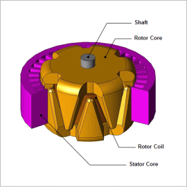
In this example, the output voltage and field current of a claw-pole type alternator is checked when the rotor speed is changed.
Control Circuit

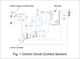
The control circuit is shown in Fig. 1. The command value is set to a voltage of 12 V, and the current controller is connected to the field winding of the alternator. The initial value of the alternator is set at 2400 r/min, and at 0.1 sec later changed to 1800 r/min.
Rotation Speed Waveform, Output Voltage Waveform, and Field Current Waveform
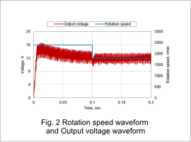
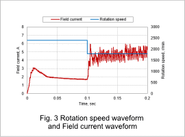
Fig. 2 shows the rotation speed waveform and the output voltage waveform, and Fig. 3 shows the rotation speed waveform and the field current waveform.
From Fig. 2, it can be seen that the output voltage is kept at 12 V even if the rotation speed changes. This is because, as shown in Fig. 3, when the rotation speed decreases, increasing the field current increases the flux linkage of the coil and increases the output.


