Overview
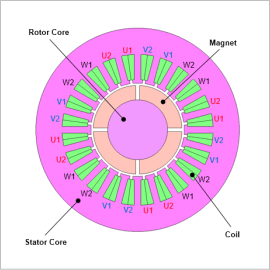
For example, for power supplies there are 6-phase motors with 3-phase double windings that use two inverters, having a 30 deg phase shift in electrical angle. From this, by using multiple inverters, enhanced redundancy of the in-vehicle motor system is achieved. The motor system can be stopped safely without falling to be in an uncontrollable state even if a failure occurs in a part of an inverter. However, circuit simulation is necessary to accurately evaluate safety.
When an inverter malfunctions, from overcurrent flowing and from the range of the magnetic field in and around the steel plate where the magnetization properties are nonlinear, inductance exhibits nonlinear behavior as well. Because of this, a highly accurate plant model cannot be created using only linear methods. In JMAG, it is possible to create a plant model that models actual motors in detail taking into account magnetic saturation characteristics and spatial harmonics exhibited in motors.
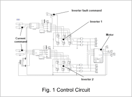
In this example, a JMAG-RT model of a 6-phase SPM is loaded into a control/circuit simulator, and circuit simulation for an inverter failure is carried out.
Control Circuit
Current Waveform, Torque Waveform
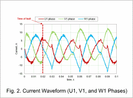
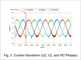
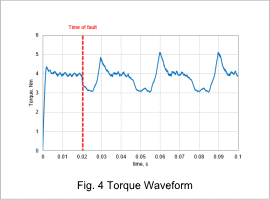
The currents for the U1, V1, and W1 phases, for the U2, V2, and W2 phases, and the torque waveform are shown in fig. 2, fig. 3, and fig. 4 respectively.
From fig. 2, it can be seen that the U1-phase current decreases somewhat after the occurrence of the fault, and overcurrent flows through the V1-phase and W1-phase coils. Meanwhile, from fig. 3 it can be seen that the U2-phase, V2-phase, and W2-phase currents are stable.
As shown in fig. 4, although the torque exhibits a large periodic ripple after the fault, its size remains steady. From this, it can be judged that the motor system can safely be brought to a stopped state without falling into an uncontrollable state.
