Overview
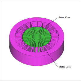
When operating a synchronous reluctance motor (hereinafter referred to as a SynRM), since the nonlinear range of the magnetization properties of an electromagnetic steel plate is used, inductance also exhibits nonlinear behavior. Because of this, a highly accurate plant model cannot be created using only linear methods. In JMAG, it is possible to create a plant model that models actual motors in detail taking into account magnetic saturation characteristics and spatial harmonics exhibited in motors.
In this example, circuit simulation is carried out simulating the control of current and speed by loading a JMAG-RT model for a SynRM into a control/circuit simulator. In addition, comparison with an ideal motor model is performed.
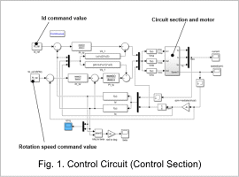
Control Circuit
Rotation Speed Waveform, d-Axis Current Waveform
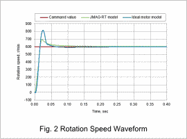
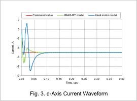
Fig. 2 shows the rotation speed waveform for a JMAG-RT model and an ideal motor model, and fig. 3 shows the d-axis current waveform.
It can be seen that both converge to the command value. Moreover, it can be seen that there is a difference in behavior between the two as regards the overshoot.
Coil Current Waveform, Torque Waveform
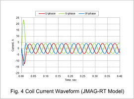
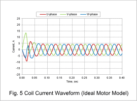
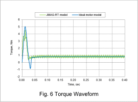
The coil current waveforms when using the ideal motor model and the JMAG-RT model are shown in fig. 4 and fig. 5, and the torque waveform is shown in fig. 6.
Regarding the rise, the JMAG-RT model has more current flowing, but the torque being generated is lower. This is due to the magnetic saturation of the core being precisely taken into account. In addition, looking at the steady-state torque waveform, it can be seen that there is torque ripple due to spatial harmonics.
