Overview
JMAG-RT Model can simulate the effect of harmonics on the system and magnetic saturation effect that are calculated from FEA.
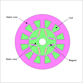
In this example, we introduce the case study that simulate the fault of an IPM motor using JMAG-RT. The fault simulated in this case study is an open circuit fault which is caused due to failure of an IGBT, this is one of the most commonly occurring faults in PMSM operation.
Fault Description
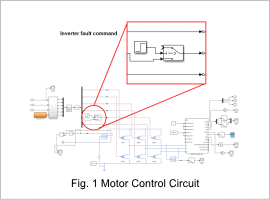
The fault occurs due to an IGBT failure at 0.3 sec into operation start.
This causes an open circuit in the six step inverter. This causes the current through that particular IGBT to fall to zero.
We are particularly looking for the effect of this kind of fault on the torque and current characteristics of this motor.
Fault Analysis
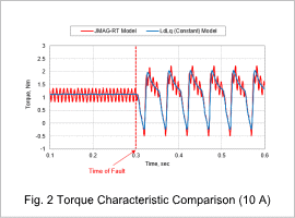
There is a fundamental difference between the high fidelity model (JMAG-RT Model) and low fidelity model (LdLq (Constant) Model). The JMAG-RT model take into account the angular position of the current vectors. This requires FEA. Thus with JMAG-RT model it is possible to capture torque ripple before and during fault.
This is beneficial in prediction of motor behavior due to a IGBT fault while doing a system analysis. The torque behavior is demonstrated in Fig. 2. The point at which the fault occurs is also visible. By running higher time resolution analysis on such a model it is also possible to predict the phenomenon while reclosing or after fault is resolved.
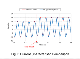
This difference can also be observed in the current waveform after the fault occurs. From Fig. 3, the difference in currents is minimal this causes the difference in the average values of torque for two models to be minimal.
Fault Analysis at Higher Loading
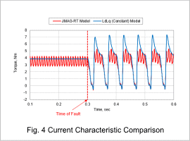
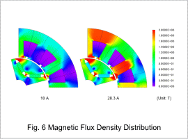
There is a difference between the average values of torque when using LdLq (Constant) Model and JMAG-RT Model in Fig. 4. This difference is however not observed in Fig. 2. The main difference here being the supply currents. Fig. 2 has 10 A while Fig. 4 has 28.3 A.
The reason behind this difference is the saturation effect, this can only be observed in the JMAG-RT Model and not the LdLq (Constant) Model.
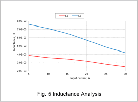
From Fig. 5, the values of Ld and Lq decrease as the input current increases. This happens due to the cores being saturated . Due to saturation the Iron in the cores starts acting like air. This causes a decrease in the average torque observed in Fig. 5. The saturation can be observed in FEA from Fig. 6.
The behavior prediction in the fault thus also depends on characteristics not observed by a simple LdLq (Constant) Model thus it is useful to use a High Fidelity one.
