Overview
The change in driving force from the change in actuator positions greatly affects the positioning accuracy. Furthermore, the driving force is controlled by the current. Moreover, because of the nonlinearity of the material and due to the magnetic path not being fully contained in the magnetic material, it is difficult to calculate by hand the driving force for each current value and position of the voice coil motor. Therefore, taking into account dynamically changing characteristics, in order to control the voice coil operating at high speed, a plant model containing characteristics dependent on magnetic saturation and the position of the mover is required.
JMAG-RT can create a highly accurate plant model in a JMAG-RT model by performing FEA taking into account the geometry, materials, and driving conditions, and extracting the characteristics of the voice coil motor.
In this example, circuit simulation is performed to control the position of a mover by loading a JMAG-RT model for a voice coil motor into a control/circuit simulator.
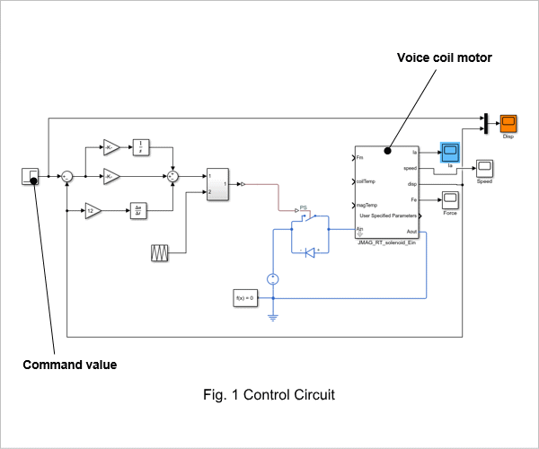
Control Circuit
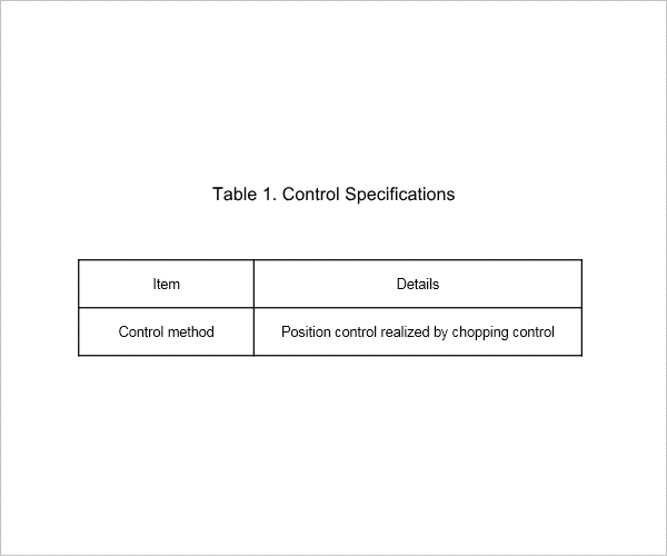
The control specifications are shown in Table 1. The control circuit control section is shown in Fig. 1.
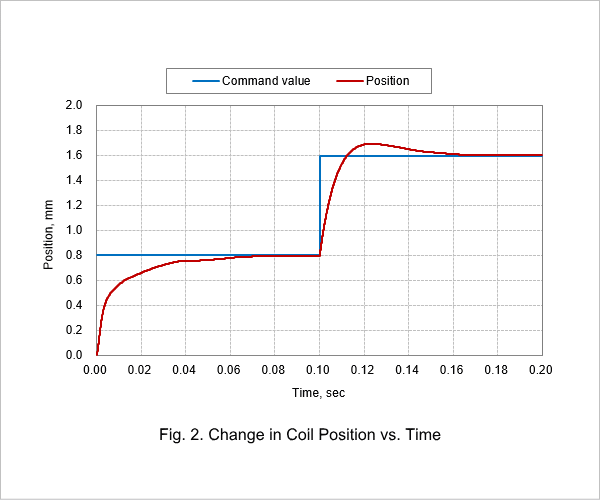
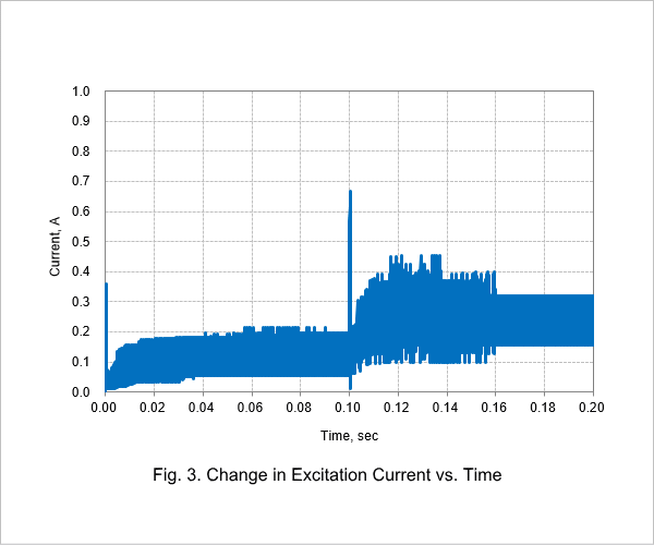
Change in Coil Position vs. Time
Fig. 2 shows the coil position vs. time, and Fig. 3 shows the excitation current vs. time.
As shown in Fig. 2, the movement from the 0-mm position to the 0.8-mm position and the movement from the 0.8-mm position to the 1.6-mm position are both a movement of 0.8 mm, but the electromagnetic force is different, and the trajectory of the movement is different because it is dependent on inductance current and on position and is influenced by the spring.
From Fig. 3, it can be seen that a surge current is generated the moment the coil starts to move. Since surge current may damage peripheral electrical equipment, examination of this equipment is necessary when it is excessive.