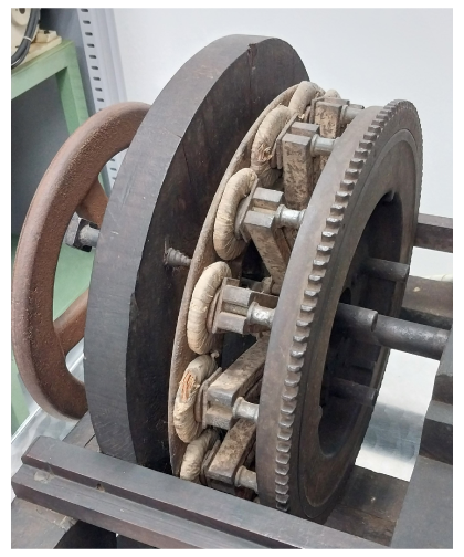
Fig. 1 Axial-flux machine in the WEG museum, Jaragua do Sul, Santa Catarina, Brazil 1
Sometimes I get a request to have a look at a disused electric machine in an old factory or even in a barn. Often the question is ‘does it work?’, or ‘can we make it run on single-phase AC?’, or ‘is it worth anything?’ I’ve seen a few induction motors and one Schräge motor and an inductor alternator, all of them long since scrapped. But the one in the photo was easy to find in the WEG Museum at Jaragua do Sul in southern Brazil, many years ago, and it’s a jewel for one reason in particular: it provides a perfect graphic demonstration of Faraday’s law. Imagine my delight when I came across it, in the company of a group of friends and colleagues from Jaragua do Sul.
We need to look for magnets rotating past coils of wire. Faraday tells us that the rotation induces voltage at the terminals: that’s the basis of the electric generator.
In the axial-flux machine in the photo, there are 12 magnets mounted on a toothed wheel which may have been geared to a water-wheel or some other engine or ‘prime-mover’. The magnets are probably formed from U-shaped steel bars, with slots at the outside ends to accept fixing bolts to the toothed wheel. The U-shaped steel bars will be magnetized N-S, so they drive flux through the circular coils which appear to be attached to a thin steel plate. The coils appear to be insulated with cotton tape. The U-shaped steel bars have another refinement in the form of a small steel plate which probably acts as a flux-spreader, providing a slightly more uniform air-gap close to the coils. It is noteworthy that the number of coils is equal to the number of magnets.
When the magnets rotate, there will be a cyclic variation in the flux-linkage of each coil, and Faraday’s law tells us that the generated or induced voltage will be equal to the time rate of change of this flux-linkage. It really is just as simple as that.
To understand this from a physical point of view, we have only to imagine flux from one of the magnet poles threading its way through one of the coils, back through one of the adjacent coils, and back to the adjacent magnet pole. It’s intuitively obvious that the amount of flux-linkage (turns × flux, if you like) will vary as the rotor rotates. Given the alternation in the fixed polarity of the magnet poles (NSNSNSNSNSNS), it is also obvious that the voltage waveform will be an AC waveform, with alternate positive and negative half-cycles. Moreover, the fundamental frequency in this waveform will be six (i.e., the number of pole-pairs) multiplied by the number of revolutions per second of the wheel. We therefore have a physical description of the most important essential features of an AC generator.
The coils are probably connected in series to form a complete winding, so that the terminal voltage is the sum of the coil voltages. We can see from the configuration that the induced coil-voltages will all be in phase,2 so the total voltage will be 12 times the voltage of a single coil, and there can be only one phase; in other words, there is no question that this might be a three-phase or any other kind of polyphase machine. Moreover, since there is no commutator there is no possibility of frequency conversion to DC (zero frequency) or any other frequency. Nor is there any means of controlling the excitation (since it relies on permanent magnetism). The only means of control is (possibly) the speed of rotation and/or (possibly) the impedance of the load.
The age of this generator is probably at least 100 years, and possibly 150 years. So it is not disrespectful — indeed it could be said to be educational — to make some critical comments about its effectiveness. Educational, because such comments will draw attention to the principles of design and analysis that have been painstakingly accumulated since this machine was first put together. 3
1. The U-shaped steel magnets will be weak. Although steel may have a remanent flux-density above 1 T, its demagnetization curve in the second quadrant of the BH loop is very ‘soft’, so that it is easily demagnetized. In the generator in the photo, it will be working on a ‘load line’ (representing the demagnetizing effect of the overall flux-path outside the magnet) whose permeance coefficient will be quite low, so that the flux-density at the magnet poles may be only of the order of 0.5 T or even less. The flux-density in the centre of each coil will be still lower. We cannot tell if the coils are wound on soft-iron bobbins, or what. The result of a weak magnetic field linking the coils will be a relatively low generated voltage.
2. There is really no definite magnetic core, although there are some bits and pieces of (presumably soft magnetic) steel in the fixtures. The absence of a designed-to-purpose core will not only reduce the generated voltage (as discussed above), but it also means that there is considerable leakage: in other words, poor magnetic coupling between the field source and the stator coils. The reactance of the stator winding will also be very low, and mostly composed of leakage reactance. Indeed it may be so low that the resistance of the winding is the dominant component in the stator impedance, which determines the voltage drop when load current flows.
3. Concerning the waveform of the generated voltage, at first we might expect it to be rather poor, without any definite shape, because it seems that workshop convenience was the main factor in putting the machine together; there is no obvious evidence of detailed electromagnetic design as we would see it today. However, it is a general rule-of-thumb that in a largely air-cored device of this type, the higher-order space-harmonics of the flux-density distribution decay quite quickly with distance from the magnet poles; and on this basis we should not be surprised to find that the generated voltage waveform is relatively close to a sinewave.
4. There is no housing. The electrical and magnetic parts are exposed, so they are vulnerable to mechanical damage (to say nothing of rain if the machine is out of doors, or of chemical splashes if it is in a factory or even on a farm). While it is fun to see all the working parts in a museum exhibition cabinet, exposed terminals and rotating parts would nowadays be seen as serious shortcomings from the point of view of safe and reliable operation.
5. Along with the absence of a housing, there is no cooling system: the only cooling is by natural convection of the surrounding air with perhaps a tiny element of conduction and radiation. The temperature in southern Brazil can be 40 C, so we can safely say that the machine is not well cooled. This will impose a limit on the safe working current. Coupled with the low generated voltage, the power will be low for a machine of its size.
Note that if we force current into the winding against the induced voltage, we turn the generator into a motor. The law of conservation of energy suggests that ‘power in’ equals ‘power out’; i.e., current × voltage equals torque × speed. So electric machines are energy converters. The process is never 100% efficient, so we always get power losses which appear mainly as heat in the copper windings and the steel core. Power losses don’t just disappear (they must obey the law of conservation of energy) and they have to be accounted for and paid for.
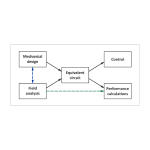
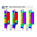
In order to bring the machine in the photo up to modern standards of power density, efficiency, and durability, we would need a comprehensive suite of design tools (such as JMAG) as well as a solid basis in manufacturing and the use of modern materials. The steel core would be laminated (or possibly made of compressed powder), while the magnets would be replaced by high-coercivity magnets such as NdFeB (for high power density) or ferrite (for lower power density). Probably the stator coils would be more compact with much better insulation (both the magnet wire and the coil insulation), and the thermal diffusion paths would be improved.
Because the configuration is unavoidably 3-dimensional with no possibility of an accurate 2-dimensional model, we would need 3D finite-element analysis from the start, even to calculate the most basic parameters such as the generated voltage and its waveform on open-circuit. With current applied under load conditions, 3D magnetostatic analysis would be used to determine the torque as well as its time-waveform. Beyond these basic calculations, as is well known, there is a series of advanced processes to compute accurate core losses and parasitic losses due to eddy-currents. The CAE processes also include thermal analysis and simulation of the operation in conjunction with a power-electronic controller, perhaps extending into the wider interconnected system beyond the machine (in both electrical and mechanical aspects).
None of these levels of sophistication could have been foreseen by the ingenious engineer who built the machine in the WEG Museum. Although the theory of magnetic fields and electric circuits was beginning to be developed in the late 19th century (the probable date of the machine), it took several years before they were formulated in a way that could readily be used in machine design. Most of the materials that would be used today were unknown or in a rudimentary state of development, while many of our modern manufacturing processes would be beyond the dreams of that ingenious engineer.
The WEG machine is a fine example of the early history of electric machines and a clear ‘demonstrator’ of Faraday’s law. Indeed it demonstrates many other principles of electric machine design, including the characteristics of permanent-magnet machines. If I were starting out as a young college professor, I would have at least one modern replica in the undergraduate laboratory — almost certainly with modifications to show the effect of such things as series/parallel connection; polyphase winding arrangements; rectification of the output or driving the machine with an inverter; and an almost unlimited list of others.
The history of electric machines is rich in terms of basic configurations and embellishments of all kinds, and there is a vast literature recording them. In many cases the electromechanical complexity was far greater than anything we see today. There is nothing like the Schräge motor in current production! What we see today is a relatively narrow selection of machine types, often refined to a high degree with advanced materials, advanced manufacturing methods, and advanced CAE; while the physical complexity has migrated into the control system and the electronics. Because of this, the simple toplogical configuration of the WEG motor is surprisingly close to the modern axial-flux machine — not because of the prescience of its inventor and certainly not because of any simple-mindedness in today’s designers, but fundamentally because of the arrival and exploitation of new materials (principally Silicon and high-coercivity magnets) that were unknown in the late 19th century, when only copper and steel were available.
Notes
1 https://museuweg.net/. Highly recommended! The photo was kindly supplied (with permission) by Carlos E.G. Martins of WEG, together with supporting comments. Dr. Cláudia da Silva also commented that one of the WEG founders was passionate about farmers’ water-mills and this kind of generator may have been one of his first designs in the beginning of WEG history. It has not been possible to verify this in detail but it reflects the rich detail to be found in the WEG museum (and indeed in other electrical and industrial museums). The physical form of the permanent magnets is not at all clear, but I have assumed that both ends of each U-shaped steel bar have the same polarity, giving 12 poles in total. In that case the U-shaped bars are not like the popular image of a ‘horseshoe’ magnet, whose ends have opposite polarity. It is also possible that the magnets are actually formed from the studs running in an axial direction from the toothed wheel to the thin rectangular plates on each pole.
2 That is, in precise synchronism with each other. Note the two different meanings of the word ‘phase’ in this paragraph. One refers to the properties of the EMF waveform, while the other is a physical component or section of the windings.
3 If I were teaching a class in an apprentice school or a college, I would love to set this as a class exercise!