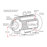
Fig. 1 Bits of the design conundrum
How many parameters are needed to determine the dimensions of an electric machine?
Let’s define the minimal set of machine dimensions to include the outside diameter and axial length of the stator core, and nothing else. With only two dimensions, that set is clearly minimal. A smaller defining set (other than the null set) would have only one dimension, and that would have to be the weight or possibly the price. But neither of these defines the size. It appears that two is the smallest number of critical dimensions required to define the size. Even then, two dimensions are sufficient only to describe a predefined shape, in this case a right circular cylinder. Enough for a beer-can, maybe, but what about the rotor diameter, the axial length including the end-windings, the shaft diameter and length, and many other dimensions necessary to define the housing? The number of dimensions quickly proliferates as the ‘design’ evolves from a rough outline to a complete blueprint. In the end, we will be able to count hundreds, maybe thousands, of parameters or items of data in the definitive description of a complete machine.
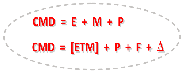
The total dataset of a machine can be large or very large, but it is never small. It can be organized into categories and expressed as an equation (Fig. 1)
CMD = E + M + P
where CMD means ‘the complete machine design’, E means the electromagnetic design, M means the mechanical design, and P means the aggregate of material properties for all the different components. The plus sign implies ‘combination’ or ‘union’, not simple summation. This expression makes it look as if the E, M and P categories are independent. It is true that we have specialists in these areas, but even in small companies it is rare for one engineer to work the details in all three of them. Generally, a lot of people are involved in a given machine design, and not necessarily at the same time.
Nowadays we can think of the E and M categories as activities that begin on the computer with specialist computer programs that are continually evolving. But the P category requires physical measurement and a lot more know-how that starts with mining and encompasses all manner of material-processing operations. The design specialist in E or M is utterly dependent on the providers in P. He or she may, in the first instance, think of P in terms of a database of available materials and their properties. A designer may well use this database as a convenient personal notebook. But behind it is a great deal of know-how, widely distributed throughout the industry.
A better and more modern way to characterize the ‘complete machine design’ and the process behind it is to write (Fig. 1)
CMD = [ETM] + P + F + Δ
This reflects the fact that thermal design T is nowadays treated with detailed expert technological attention, commensurate with the level of skill and sophistication in the E and M categories. The bracketed expression [ETM] underlines the close interdependence between these three important categories of design activity, and the need to treat them together. In the past, thermal design may have benefited less from the numerical solution of differential equations and depended more on physical testing and rules of thumb. Actually the same is true in the E and M categories, but for many years it seemed that the thermal aspects received less attention in academic and research institutions.
P is still there as one of the core elements in the data structure of the design process.
We also have another category : F, for ‘factory know-how’. A stunning example of this is what the automotive industry has done with hair-pin windings. Automotive engineers? Designing electric machines? You bet. In simple terms, what they did in the last 20 years was to double the slot-fill factor and the electric loading — an advance that the electrical gurus would not have thought credible a generation ago. In fact every factory is critically dependent on the F category of design know-how and data. The F category is closely linked to the M category, but it is not detached from the E and T categories.
Finally the design ‘equation’ has a term Δ that represents tolerances and variations in all the other categories. We only have to look at an engineering drawing of the simplest component to see the notation ‘+/−’ that reflects the permissible variation in the dimensions of manufactured parts. A ‘design’ is not defined by its nominal parameters but by the total set of nominal parameters and tolerances. The tolerances enlarge the design data-set considerably. They do not simply represent ‘lee-way’ or ‘permitted slackness in the dimensions or other properties of manufactured parts’. They are often critical, and they require detailed consideration in relation to all the other aspects of the design data in the E,T,M, P and F categories. Furthermore, tolerances may not always been known a priori. We can (and may have to) extend the Δ category to include a very wide range of unknowns.
Returning to the original question, how many parameters. . ., Professor Lawrenson once said that you need about 100 parameters to design a complete machine. As a lowly postgrad., I remember being horrified at such a level of complexity. He also said that you could design a synchronous machine with about 160 lines of Fortran code. (Calm down, folks : that was in the day of punched cards). Interestingly, at that time (the 1970s) there was considerable interest in optimization. Books were written, and engineers experimented with ‘penalty functions’ and ‘hill-climbing’ and ‘Monte Carlo’ methods. We will never know if this was motivated by the hope of reducing the engineer’s work-load, or how much difference these methods actually made. This was in the days long before finite-element methods revolutionized the accuracy and practical scope of electromagnetic calculations (while also slowing them down!) We can therefore trace back a long way to the origins of ‘big data’ and automation in the design process.
In my own career I have been lucky enough to work in some environments where there were arguably too many resources, and others where there were not enough. In all cases I’ve been limited by my own brain power, and late in life I have returned to the fascinating ‘how many parameters’ question — what does it take to fix the design of an electric machine? My answer is about 60, of which about a quarter are sufficient to determine the main dimensions of the stator and the rotor and the winding. This number (which, it is admitted, is somewhat subjective) is based on the idea of a design that is sufficiently complete on paper to warrant the building and testing of a prototype. I would say (wouldn’t I) that my 60 parameters are roughly sufficient for a colleague in mechanical engineering and/or manufacturing to ‘go away and produce a prototype’. So the figure of 60 parameters is the set that defines my own limitations — the boundary of my competence, beyond which I must collaborate or seek help. Of course I’m speaking of work in a small company (or in a small group in a larger company), where the association between engineers and shop-floor experts may be looser than in a sophisticated, large, expensive project. Those big projects require tighter control of all the details, including more documentation — more parameters, more data. Whether or not they get that control, and how they get it, is obviously a matter for project managers.
Once a prototype is built and available for testing, it becomes possible to measure the performance and many of the parameters that would otherwise have to be calculated (by whatever software might be available), or remain unknown. The point of departure at which simulation is regarded as sufficiently complete to warrant building a prototype varies greatly from one company to another, depending on their facilities, staff skills, and various other factors including the time-scale and the costs involved.
60 is still a large number of parameters to the practical engineer faced with a design requirement. There arises the question of finding an orderly progression through the design process. It is obvious that this cannot be uniquely formulated, because the set of requirements is case-dependent and often incomplete; and elements of it often have to be negotiated or renegotiated with a customer. However, certain bare-bones details are common to all the machines in a particular class of machines (such as the IPM), and this does give rise to the possibility of a formal procedure: a step-by-step process in which the required parameters are calculated one by one, starting with a basic set of ‘input’ parameters and following a kind of hierarchy of dependencies.
Fortunately there is some flexibility in the hierarchy of dependencies. As a simple example, suppose we need to determine the dimensions of a rotor, in terms of its diameter D, length L and volume V. Any one of these three parameters can be uniquely determined, given the other two. We could say that there are three possible ways to formulate the ‘design problem’ for this rotor. The only constraint is that two out of the three must be given — any two. To be a little more precise, we should also state the assumption that the rotor is a right circular cylinder. If this is not the case, then what is meant is the swept volume as the rotor rotates. Either that, or the rotor is whirling and you need to get out of the way as quickly as possible!
Proceeding to a complete machine design with, say, 60 parameters, the hierarchy or network of dependencies will be more complicated. It will also define itself in terms of groups of parameters, not necessarily the whole set. In other words, a given parameter may depend only on a subset, even a small subset, of the total number of parameters. The idea of independent groups of parameters is an appealing simplification: the parameters within any group are to some degree dependent on one another, while parameters from different groups are relatively independent of one another.
There may be a mathematical formulation for the hierarchy of dependencies in an electric machine. I have no idea what it looks like. I would say it comes down to experience and common-sense logic (but then I’m old). For example, suppose I am part-way through a design calculation and I have reached a point where I know the slot size and the slot number, and I know what the electric loading must be to achieve a given level of torque. Experience and common-sense logic tell me that I must now find a combination of two new parameters, the current-density and the slot-fill factor, consistent with these values. This conclusion is itself an obvious expression of the local hierarchy of dependencies, but it continues in the form of the constraint that the current-density and the slot-fill factor cannot be assigned independently. Don’t we just love to make rules! The whole design process is a complex network of such rules.
But in that example, how do I assign suitable values for the current-density and the slot-fill factor? In the early stages of a design, these factors will often be empirical. In other words, I will begin with values that I know from experience have worked before. My choices — if approved by my supervisor and maybe even by the customer — will have consequences. The current-density will play a large part in the temperature-rise, the life, and the efficiency. As for the slot-fill factor, somebody in the factory (maybe a machine) has to insert the wires in the slot. The difference between a feasible and a non-feasible slot-fill factor can be quite small, and it may be critical. Given all the other constraints which apply to the design and the manufacturing process, we might find that 0.32 is comfortably achievable, 0.33 barely possible, and 0.34 impossible.1
We can see from this that the design process is more than a programming exercise. While software can help to organize, store, process, and display some of the relevant data, we also need judgement, experience and measurement; all of which are to some extent indefinite, and all of which are often extended by invention and tests (including elaborate tests of complete prototypes, sometimes with considerable risk involved).
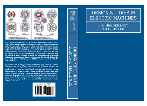
Ref. [2] describes in more detail a basic process for a designing an IPM and several other machines with a limited number of parameters, following a set of local hierarchies of dependencies which divide the process into manageable parts (which, however, remain consistent with each other). There isn’t room to describe it here! But I would also like to point out that this is what the Blue Book is all about, [2]. It’s about the core electromagnetic design according to classical principles, closely integrated with the finite-element method to ensure reliability in the electromagnetic design data. Whether the number of parameters is 15 or 100 or 10,000, the essential classical theory has not changed and will not change; and this theory is laced with hierarchies of dependencies that help to define the intellectual structure of the design process. As the sophistication and complexity of the design process increases, it remains important not to lose sight of this structure.
Notes
1 When I hear about slot-fill factors of 70-80%, I think one of two things. One: it was not achieved in any factory in my experience. Two: it might have been defined by another formula. For example, in some cases the slot fill is defined using the square of the insulated wire strand diameter times the number of strands per slot, divided by the available slot area after slot-liners, separators, and top-sticks have been accounted for. That’s an engineering formula if ever there was one!
Further reading
[1] J.R. Hendershot & T.J.E. Miller, Design of Brushless Permanent-Magnet Machines, Motor Design Books LLC, 2022, sales@motordesignbooks.com ISBN 978-0-9840687-0-8.
[2] J.R. Hendershot & T.J.E. Miller, Design Studies in Electric Machines, Motor Design Books LLC, 2022, sales@motordesignbooks.com ISBN 978-0-9840687-4-6.
Mainly of historical interest . . .
[3] E. Levi, Polyphase Motors; A Direct Approach to their Design, John Wiley & Sons, 1984, ISBN 0-471-89866-X
[4] H.C.J. deJong, AC Motor Design with Conventional and Converter Supplies, Oxford University Press, 1976, ISBN 0-19-859321-X
[5] C.G. Veinott, Effective Use of a Personal Computer for Small Apparatus Design and Other Engineering Uses, IEEE Trans., Vol. IA-24, No. 4, July / August 1988, pp. 560–567
[6] A.S. Meyer and C.F. Landy, The Structure of an Induction Motor Calculation Program for Non-Technical Users, Conference Record of the 1991 IEEE Industry Applications Society Annual Meeting, Dearborn, MI, USA, 1991, pp. 28–34 vol.1, doi: 10.1109/IAS.1991.178128