Contents
1. Introduction
2. Unique Characteristics of Differential Equation and Integral Method Models
3. Accuracy Validation
3.1 Motor and LUT Used in the Validation Process
3.2 Accuracy Validation Using a Star Connection and Standards Sinusoidal Drive
3.3 Accuracy Validation Using a Star Connection and Sinusoidal Drive with the W-phase Disconnected
3.4 Accuracy Validation Using a Star Connection and PWM Drive
4. Conclusion
5. References
1. Introduction
JMAG-RT generates models that can simulate nonlinear motor characteristics for use in control circuit designs done with software-in-the-loop (SIL), hardware-in-the-loop (HIL), and other such testing methods. JMAG-RT provides a wide variety of these motor models, but the PMSM motor model is currently the most widely used. In particular, two types of precision spatial harmonic motor models can take into account the spatial harmonics produced by the geometric properties of the stator, slot openings, and other motor components. This white paper compares the analysis accuracy of these two spatial harmonic motor models via numerical tests. The simulations and measurements evaluate a motor with a three-phase star connection driven by a standard sinusoidal drive, a sinusoidal drive with the W-phase disconnected, and a PWM drive.
2. Unique Characteristics of Differential Equation and Integral Method Models
The discretization differentiates differential equation and integral method models. Differential equation models convert the three-phase voltage equations simulated as differential formulas in a standard coordinate system into discretized equations representing the magnetic flux and differential inductance. The simulations solve these equations while referring to the lookup tables (LUT) packaged with the differential equation model. The LUT are obtained by running a finite element analysis (FEA) that takes into account the detailed motor geometry, nonlinear material properties, and relative positions of the stator and rotor, which enables these voltage equations to simulate the intricate behavior of a motor.
Conversely, integral method models convert the frame of reference for the three-phase voltage equations to the direct-quadrature-zero (DQ0) axis. Analyses obtain the positive current as an unknown variable using LUT for the magnetic flux by integrating and converting the voltage equations over time into magnetic flux equations. Designers need to prepare LUT for the magnetic flux in advance through the inverse conversion of LUT created using differential calculus.
3. Accuracy Validation
3.1 Motor and LUT Used in the Validation Process
The accuracy validation uses the JMAG-RT RTML025 motor model (Fig. 1) provided on the JMAG website. This case study runs tests on this motor with a three-phase star connection driven by a standard sinusoidal drive, a sinusoidal drive with the W-phase disconnected, and a PWM drive. FEA to obtain accurate results and create the LUT use the mesh model presented in Fig. 2. The HB point sequence is outlined in Fig. 3. The mesh model has over 120,000 elements while the HB point sequence simulates the magnetic flux density up to 2.7 T using a sequence of 257 points, which is excessive for two-dimensional analyses. However, this case study uses this mesh model and point sequence to eliminate as much discretization error as possible. The LUT for the differential equation model has a current amplitude resolution with 30 points from 0 to 369 A, a current phase resolution with 37 points from 0 to 360 degrees, and a mechanical angle (pitch) of 0.46875 degrees. JMAG automatically generates the LUT of integral method models through the inverse conversion of current and flux tables created using differential calculus. The settings in this case study create magnetic flux and current tables that divide the D-axis as well as the Q-axis magnetic flux into 40 unequal parts.
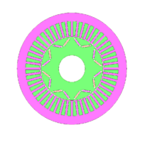 Fig. 1. IPM Motor Model for Analysis
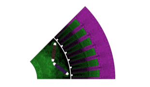 Fig. 2. Mesh Model for Analysis
(1/8th two-dimensional model: 122,513 elements)
![Fig. 3. HB Point Sequence for Analysis (257 points up to 2.7 [T])](/images/whitepapers/w-mb-181c_e.gif) Fig. 3. HB Point Sequence for Analysis
Fig. 3. HB Point Sequence for Analysis
(257 points up to 2.7 [T])
You need to sign in as a Regular JMAG Software User (paid user) or JMAG WEB MEMBER (free membership).
By registering as a JMAG WEB MEMBER, you can browse technical materials and other member-only contents for free.
If you are not registered, click the “Create an Account” button.
Create an Account Sign in


