JMAG’s Role in Supporting the Electrification of Compact Vehicles
Suzuki’s newest Solio model is equipped with a mild hybrid system. For compact vehicle electrification, simply adding electric components cannot improve fuel consumption sufficiently. To elicit maximum performance without wasting magnetic circuits, JMAG is used to carefully identify magnetic flux flow occurring in the rotor of a permanent magnet synchronous motor (PMSM). We spoke with Dr. Aoyama, Mr. Akaki, and Mr. Deng from the Electric Component Development Department regarding means to reduce costs and motor weight, as well as the difficulty in compact vehicle electrification.
Specific Difficulties with Compact Vehicle Electrification
Aoyama:
I work in a department for developing automotive components (motors, inverters, batteries, etc.) for electric vehicles such as for hybrid electric vehicles (HEV), and electric vehicles (EV), including the control of some of those components. Our main roles are the development of drive motors and assist motors for HEVs and EVs. I primarily work on the research and development of advanced motor technologies. I evaluate magnetic circuits in magnet free motors which produce torque equivalent to PMSMs. I also evaluate biaxial motors. Mr. Deng is mainly in charge of the development of PMSM, so that we can eventually utilize it in our in-house products at Suzuki. Mr. Akaki mainly works on analyzing losses to evaluate improvements in analysis accuracy. He is also involved in increasing modeling accuracy for iron loss.
Aoyama:
If you take a look at the recently released Solio mild hybrid, I think you’ll have your answer. Especially for compact vehicles, we must consider the trade-off between improved fuel consumption that comes with electrification and the decreased fuel efficiency due to an increase in weight. For improved fuel efficiency due to the electrification of power trains in comparatively larger vehicles, the increased weight that comes with the larger sized vehicles doesn’t have as much of an impact on fuel consumption, so attention to weight isn’t as important. But the smaller the vehicle, the more prominent the effects of decreased fuel efficiency due to increased vehicle weight become. There are extremely important aspects to see, such as how much direct current bus voltage can be carried as a battery, or the ratio of the percentage internal combustion engines contributes to total power versus the contribution coming from electric power.
Evaluating biaxial motors also require the same considerations. To put it simply, the electrification of a vehicle increases the number of components, leading to an increase in weight. So, for example, when using a vehicle body that is not electrified as a base, it is important to think of removing some components in exchange for adding others so the total weight does not change. This is “smart” system integration. For example, conventionally we have considered how combustible energy and electric energy can be mixed using two motors and gears; however, we now think about integrating the functionality of gears and motors and consider things like “If we configure the magnetic circuits this way, we can make this possible”. I think that it’s really important to consider decreasing the size of the power train by combining and consolidating functions.
Inspiring New Designs Using Magnetic Flux Flow
Aoyama:
We are now at a phase at which design is not possible without JMAG. For automobiles especially, motors must be able to perform in extreme conditions. Motor is exposed to low temperature condition about -40℃, and also to high temperature around the engine’s heat source. To evaluate performance in these types of environments, JMAG, which uses the finite element method (FEM), is required, and it is vital to be able to view in detail the responses of motor characteristics.
Aoyama:
By visualizing magnetic paths for example, you can see which magnetic paths aren’t needed, which magnetic paths contribute to torque, and which magnetic paths contribute to losses. By mastering JMAG’s analysis functions, phenomena can be visualized. Have a look at how we proceeded with our evaluation by visualizing the magnetic paths (Figure 1). Although some design plans are skipped between the initial one and the recent one in this figure, actually, the magnetic paths have gradually improved.
In comparatively new generations, spaces are formed around the d-axis. The large difference between this and the initial V-shape is the main magnetic path flow of the armature magnetic flux vector (Figure 2). For a regular V-shape motor, magnetic flux flows along the inner-side in the q-axis direction. For example, for a current phase condition where armature magnetic flux is relatively opposed to magnet magnetic flux, which is in short a drive condition close to maximum torque per ampere (MTPA) control, the magnet becomes completely saturated and tends to no longer produce torque. This is due to the magnetic path of the armature magnetic flux concentrating around the exit. When a large space is given to the inner radius of the rotor on the d-axis to let the magnet work simply as a bypass, the magnetic path for the armature magnetic flux can be divided into two; a path which passes through the inner side and a path passing around the inner side of the rotor and going into the stator. Magnetic flux becomes less concentrated, and as a result, core weight can be reduced while keeping torque. By visualizing magnetic flux, we were able to create various paths, successfully distribute magnetic flux concentrations, and efficiently work out what was increased torque and what caused losses. This allowed us to make improvements to the magnetic circuits.
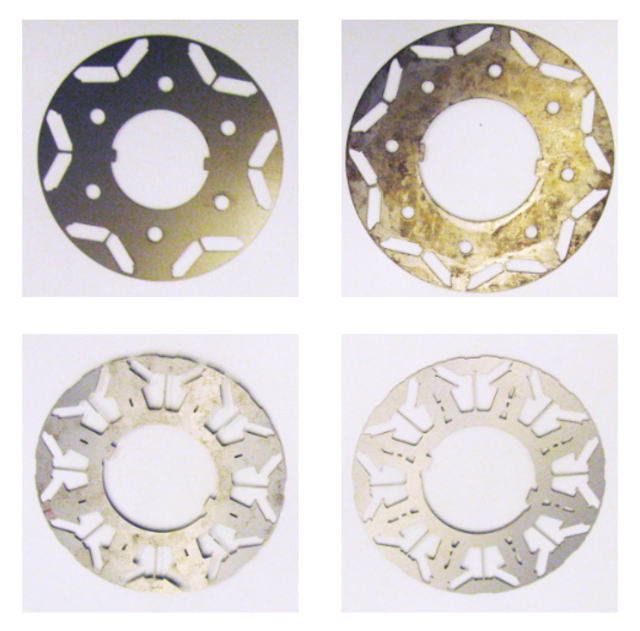 Fig. 1 IPM rotor geometry transformation
(Magnetic paths improve from the top row, left to right, and then continuing to the bottom row, left to right)
Fig. 2 Main magnetic flux vector of an IPM
M. Aoyama: “The IPM Motor Distributed Magnetic-path and had a d-axis Cavity for Optimization of the amount of Magnet”, The papers of Technical Meeting on Vehicle Technology, IEE Japan, VT-13-015(2013) (in Japanese)
Aoyama:
Another way to go about this, for example, is setting the amount of torque I want, set parameters for various dimensions for a parametric analysis, and choosing a design as the best model. Users can’t account for anything beyond what they expect, so from this point, personally I don’t see being able to explore spin-off models or other irregular models with this method. JMAG allows me to visualize magnetic flux vectors, which are usually not able to be viewed. I think it’s good to first take a good look at the JMAG window as I take a look at the magnetic flux flow going through each step. For example, I can check out magnetic flux vectors when the instantaneous value of torque ripples are at their lowest. When this occurs, I use JMAG’s function that plots magnetic flux lines separated by frequency, so I can see, “oh the third higher harmonics is doing this, the fifth is doing this, and the seventh is doing this”, while looking at the instantaneous magnetic flux vectors. While quickly proceeding through the steps, I see right at this point in time the torque waveform raises instantaneously, and the vector spiked instantaneously because the magnetic flux vector is facing this way. From the viewpoint of vibration, I want to reduce radial direction electromagnetic force; however, when seeing it from the viewpoint of torque, electromagnetic force in the radial direction is 0-order magnetic flux, and the vector needs to be oblique so it contributes to torque. I think that this is something that requires magnetic flux vectors to be viewed moment to moment. By looking at the model in detail and thinking while making adjustments to it, I think there are places that wouldn’t be recognized if performed parametrically. I think that working this way allows motor performance to be increased in the next stage.
Introducing JMAG’s Cutting-Edge Modeling Technology in Pursuit of Motor Characteristic Evaluation under Actual Driving Conditions
Aoyama:
In motor hardware design, it has not been sufficiently utilized. And I believe the optimization approach will become essential when it comes to the entire system. The examples shown were verified based on an ideal control model. In real-world conditions, when rotation reaches high speeds, the voltage utilization factor drops to 94% due to inductance, resulting in constraints of controllers. Considering these kinds of impacts from controls, the number of parameters becomes huge. I believe that optimization is effective when considering what can be done to elicit maximum motor performance including the control issues.
Aoyama:
I think that it is meaningful to handle coupling with controllers when designing a motor. However, the controllers are created based on ideal motors as their targets. On the other hand, detailed magnetic circuits are designed for motors using ideal controllers. I have been concerned about this mismatch for a while. For example, inductance is always a constant and doesn’t change for those working with controllers. In terms of temperature, they design the controllers with an ideal motor in mind, such as one with almost no temperature rise. Due to this, the mismatch for real-world motors is extremely large, and the present situation is that it is still a little difficult to connect with motor design during the initial stage of trial production. Currently, we are working on detailed analyses of phenomena under real-world driving conditions. For actual measurements, for example, when iron loss may have become larger than expected, we want to assess the reason, whether this is because of an effect due to motor hardware or an effect due to the controller. So at that time, we extract the data of a distorted current waveform from actual measurements for a motor run with a controller, and then put it in a simulation model allowing the main cause of iron loss to be analyzed.
Aoyama:
To begin with, we are working on increasing the accuracy of the analysis model of the motor. Evaluation of motor characteristics, assuming temperature and current waveform when running an actual motor, is solved with a coupled thermal and vibration analysis in JMAG. In a coupled analysis, I think it is important to determine how accurate the modeling is. With that aim, experiments on elements are conducted to isolate phenomena and conduct comparative verification with actual measurements. For example, to evaluate the degree of thermal demagnetization of a magnet, first an experiment to evaluate the amount of demagnetization in relation to temperature is performed, the models to simulate it are created, and then whether the magnet’s characteristics can be modeled is confirmed with actual measurements and analyses.
Akaki:
At present, we are at the stage of analyzing the motor multiphysics using measured physical data after repeatedly running element experiments, and we are finding out how much the analysis results differ from the actual measurements. In the future, I would like to try using completed analysis models and use JMAG to visualize the motor characteristics of an actual drive motor. I would also like to see how various external disturbances affect the behavior of a motor, and what kind of effects these external disturbances have on the inside of the motor.
Akaki:
Yes, that’s right. Although there was a slight discrepancy in the degree of demagnetization in an element experiment of thermal demagnetization; it was confirmed that the timing and conditions at which demagnetization occurs are roughly the same between analysis and actual measurement. We are considering making use of demagnetization analyses for designs in the future. Regarding the iron loss analysis of an electromagnetic steel sheet, there are many factors that influence it, such as strain due to punching that cannot be ignored, and the necessity for a method of expressing material characteristics close to the time of driving, so there are still difficulties. There are many modeling methods, but there is a trade-off between accuracy and time depending on which is chosen. Presently, in order to improve accuracy, we are working on evaluations using play models. We expect to have reproducibility. However, it takes time and effort to put the measured data into JMAG.
Aoyama:
By all means, I would like for a solution to be provided that captures actually measured data more easily.
Future Outlook and Expectations of JMAG
Deng:
We are currently running analyses of 3D models that include coil ends using rectangular wires to perform a detailed iron loss analysis (Figure 3). We are also working on vibration analysis and increasing the handling of complicated geometries such as cases with ribs. I am glad that further handling of the geometry will be improved in the future.
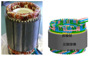 Fig. 3 Prototype Motor
(The left shows the initial stator design. The right* shows the most recent stator design which is introduced segment coil stator for using square copper wires.)
* K. Tou: “Development on Novel Stator of Traction Motor for EV/HEV Applications”, IEEJ Annual Meeting, No.5-007, pp.13-14 (2017) (in Japanese)
Aoyama:
I think that I would like the circuit components of JMAG to be enriched a little more. For instance, for the wound-field motors, which I worked on with Mr. Deng in the past, a diode commutation circuit is created on the rotor, not just a simple winding field. Instead of feeding power through the slip ring, the electromotive force caused by the spatial harmonics that is generated in the motor is rectified by the diode, and a field current is created using self-excitation (Figure 4, 5). In the future, I think by incorporating a zener circuit on the rotor or by incorporating switching components, there’s no telling what kind of motor can be made.
Also, when trying to shift from this type of new motor, PMSM to the next stage, it is necessary to advance from the initial stage, in parallel, while still taking control into consideration. I feel that we should put a little more effort into this area. For JSOL, it would be great to see the company emphasize versatile development, for example, so that RT models can be applied to numerous kinds of motors.
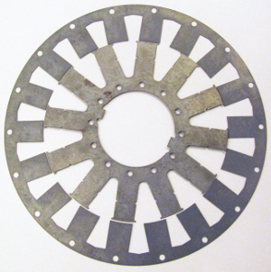 Fig. 4 Core geometry of self-commutated field winding motor
 Fig. 5 Spatial harmonic distribution
Deng:
Of course, the final goal is not loss analysis; we want to make products.
Aoyama:
As Mr. Deng has done with taking the lead in advancing development, we would like to create extremely high-performance motors, by the incremental accumulation of this kind of element technology, so that we can compete against other companies. As a final goal, we will use JMAG as a very important tool to achieve internal production.
Interviewee
 SUZUKI MOTOR CORPORATION
Electric Component Development Department
Group 1
Team Leader
Dr. Masahiro Aoyama
 SUZUKI MOTOR CORPORATION
Electric Component Development Department
Group 1
Mr. Ryosuke Akaki
 SUZUKI MOTOR CORPORATION
Electric Component Development Department
Group 1
Mr. Deng Jianing
![]()
June 1954, Name changed to Suzuki Motor Co., Ltd.
October 1990, Name changed to Suzuki Motor Corporation
Automobiles, motorcycles, outboard motors, motorized wheelchairs, electro senior vehicles, industrial equipment
Business Overview
Starting in Japan and growing their business on a world-wide scale, Suzuki develops, manufactures, and sells motorcycles, automobiles, outboard motors, electric motor vehicles, and industrial equipment. Since introducing “Suzulight”, in 1955, the automobiles that lead Japan’s electrification, Suzuki has sought to create compact vehicles. Under the slogan “Small cars for a big future”, Suzuki is creating groundbreaking products with leading edge technology.
https://www.globalsuzuki.com/

