Overview
Among the electromagnetic excitation forces, for the radial force acting on the teeth the second harmonic becomes dominant as the magnet passes by two poles in one electrical angle. On the other hand, it is known that the sixth harmonic can easily excite the zero-order ring mode which is the most likely mode to radiate sound because the excitation force of each tooth has the same phase. Because of this, for countermeasures against vibration and noise, it is useful to grasp the excitation force for each frequency component.
In JMAG, it is possible to create motor models that can model actual machines in detail taking into account magnetic saturation characteristics and spatial harmonics in the motor. By capturing this motor model, the JMAG-RT model, in a control/circuit simulator, it is possible to perform coupled simulation taking into account both the magnetic saturation characteristics and spatial harmonics of the motor and the control characteristics of the motor driver. In addition, radial forces acting on the teeth when driving the motor can be monitored providing feedback for motor design and control design.
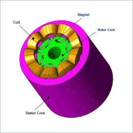
In this example, an IPM motor as a JMAG-RT model is captured in a control/circuit simulator, and radial forces acting on the teeth during motor driving is monitored while changing the operating point (current phase).
Control Circuit
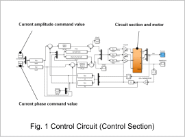
The control circuit uses the current amplitude and current phase command values, and a voltage command value is connected via an inverter to the motor.
The control method specification realizes vector control from PI control.
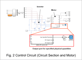
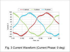
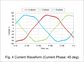
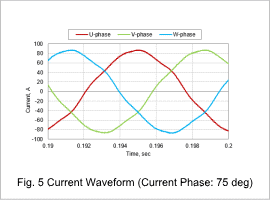
Fig. 1 shows the control section of the control circuit, and Fig. 2 shows the circuit section and the motor. The command values are current amplitude 84.8 A, and current phases of 0 deg, 45 deg, and 75 deg. The voltage command values are input to the motor via the inverter.
Current Waveform
Figures 3 to 5 show the current waveform for each current phase when the IPM motor is driven by vector control. By advancing the current phase, the magnetic field is weakened and the magnetic saturation is relaxed. As the magnetic saturation is relaxed and the inductance increases, the harmonic content contained in the current waveform decreases.
Radial Force Waveform Acting on the Teeth
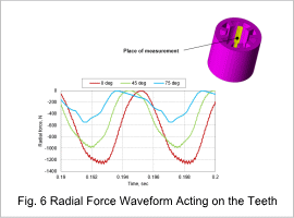
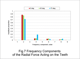
Fig. 6 shows the radial force waveform acting on the teeth for each current phase when the IPM motor is driven by vector control, and Fig. 7 shows the frequency components. In Fig. 6, when a values is negative the radial force is acting in the direction toward the center axis of the motor.
As the current phase changes, the positional relation between the stator magnetic poles and the rotor magnetic poles changes and the current waveform changes. This shows that the radial force acting on the teeth also changes. From Fig. 7, it is possible to check the radial force acting on the teeth for each frequency component.
