Overview
In JMAG, it is possible to create motor models that can model actual machines in detail taking into account magnetic saturation characteristics and spatial harmonics in the motor. By incorporating the JMAG-RT motor model into a control/circuit simulator, it is possible to perform coupled simulation taking into account both the magnetic saturation characteristics and spatial harmonics of the motor and the control characteristics of the motor driver. Furthermore, if the motor has a delta connection, circulating current flows. Since this leads to an increase in copper loss and torque ripple, it is useful to monitor the circulating current during motor driving and use the data collected to refine the control design and motor design.
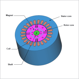
In this example, a JMAG-RT model is incorporated into a control/circuit simulator to monitor the circulating current when an IPM motor is being driven.
Control Circuit
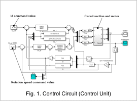
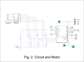
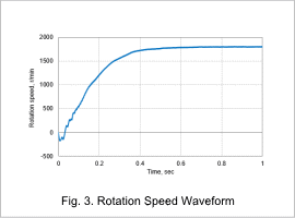
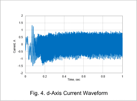
The command value is set at 1,800 r/min and the d-axis current is set at 0 A, and the voltage command value is transmitted to the motor via the inverter.
Fig. 1 shows the control circuit, a control unit, and Fig. 2 shows the circuit and motor.
Rotation Speed Waveform, d-axis Current Waveform
Fig. 3 shows the rotation speed waveform, and Fig. 4 shows the d-axis current waveform. It can be seen that both tend toward their command values.
Current Waveform
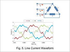
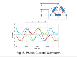
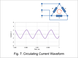
Fig. 5 shows the line current waveform at steady-state, Fig. 6 shows the phase current waveform, and Fig. 7 shows the circulating current waveform.
In a motor with a delta connection, the imbalance of the back electromotive forces causes circulating current to flow, which can cause copper loss and torque ripple.
In this example, a circulating current of about half of the line current or phase current flows, and it can be seen that its contribution to loss is large.
